Thanks Rod.
I was ruling out the long heat sinks with fins in the long direction as they generally only provide .707 the heat removal of one with the fins in the short direction (2:1 dimension).
However, if I used a small fan mounted in the middle of the heat sink I could mount it horizontally on top of the chassis and still get good heat removal.
I guess I just need to get a couple of heat sinks and take some measurements.
Another option: set up a high quality/low noise (eg Sanyo Denki) 24V fan, and supply it with the 8.5V raw dc. Quite a bit of cooling, very low noise. For instance, the 9S0924M4011 yields only 22dBA at full voltage, and you might even get away with using the 12V version and feeding in 8.5V. This kind of cooling can be very kind to any transformers or capacitors in the chassis, too.
Rod, any concerns with electrical noise from the fan getting into the filament supply in that type of setup, feeding the fan directly with the same supply that goes to your regulators?
For my Midlife Crisis amp, I'm running a completely separate 12V (adjustable) supply to the fan, with it's own transformer, filter and regulator just to be sure none of the fan-generated hash gets into any of the other supplies; I'm even putting snubbers/ferrites on the fan leads at the fan. I'm using a brushless Maglev magnetic bearing 80mm fan(33cfm at 12V).
I've got some scrap heat sinks from power supplies so I set one up with a breadboard of the coleman reglulator (I'm not about to abuse the pcbs kits I have like this).
With the heat sink vertical to get some air convection it works pretty well with a 26 degree C rise. Vin is 7.64V and the sense resistor voltage drop is 0.86 (yes, not exactly the same circuit a I adjusted it for components on hand including a different thermistor ).
The current source Vce is 2.30, and the gyrator Vce is 1.96. I need a better transformer as my supply voltage is a bit low, and have some on order. However this should be good enough to get me in the ball park.
transistor Pd for both is thus (2.3+1.96) * 2.5A = 10.65W so figure I'll need 12W per regulator times two is 24W if I'm going to use one heat sink for two channels.
It looks like a 2" X 4" heat sink with 20+ fins would possibly be enough for a less than 60 degree C rise.
Maybe something like this mounted vertically:
60x150x25mm Aluminum Heat Sink for LED and Power IC Transistor Module PBC New | eBay
Attachments
Rod, any concerns with electrical noise from the fan getting into the filament supply in that type of setup, feeding the fan directly with the same supply that goes to your regulators?
For my Midlife Crisis amp, I'm running a completely separate 12V (adjustable) supply to the fan, with it's own transformer, filter and regulator just to be sure none of the fan-generated hash gets into any of the other supplies; I'm even putting snubbers/ferrites on the fan leads at the fan. I'm using a brushless Maglev magnetic bearing 80mm fan(33cfm at 12V).
Bob, you things right, without a doubt. Still, any supply current-noise generated by the fan will be fairly low frequency, and wholly differential-mode - the Coleman Regulator deals with this very effectively.
I suspect that many DIYers will want to avoid extra trafos, and I think it can be done with a little care. The Sanyo Denki 9S0912L401 in the data sheet referred above runs 17dBA without speed reduction, and has a rated supply range of 6-13.8V, current of 70mA. At 70mA (and certainly lower for reduced speed) we can filter supply-current noise very well with a pair of ferrite chokes well into the mH range. Or, an even better way to contain current-noise at this power level would be to feed a simple current source of 80-100mA into a shunt regulator (even a TL431 circuit). With a shunt regulator, the noise current stays in a loop between the shunt and the load. And the regulator can be adjustable, to set optimal fan speed.
The fan is worth considering for many amps with enclosed chassis, as many parts dissipate substantial power - not least, the transformers.
It's about 12W through the heatsink interface, at 8.5V and 2.5A. The other couple of Watts radiate from the sense resistors and PCB radiation of the transistor dissipation. The 2A3 regulator works down to 7.5V, so if your mains supply tolerance permits, a small extra dropper resistor can ease the power a little more.
Mouser 567-517-95AB is the 517-95AB made by Wakefield. It can manage 11W for a 60 deg C rise, and is 58 x 61 x 24mm (very similar to the size you have seen). Wakefield also claims 2.0 K/W - but this is with a "300ft/min" forced convection. We must beware of headline specs, as usual.
http://www.mouser.com/ds/2/433/wakefield pwr semi heatsink-202130.pdf
So, a slightly bigger sink is needed, or mount it on some chassis with the sink on the other side; or use two of this approximate size (ebay) heatsinks mounted on a spreader bar of Alu (Alu bar is usually low cost on ebay, and a 3 .. 5mm thick stick of Alu makes a fine heatsink mounting interface)
UK vendor example:
Aluminium Flat Bar / Plate widths from 1" to 1.5" many thicknesses and lengths | eBay
30mm x 150mm (or more) and 5mm thick is good value.
Another option: set up a high quality/low noise (eg Sanyo Denki) 24V fan, and supply it with the 8.5V raw dc. Quite a bit of cooling, very low noise. For instance, the 9S0924M4011 yields only 22dBA at full voltage, and you might even get away with using the 12V version and feeding in 8.5V. This kind of cooling can be very kind to any transformers or capacitors in the chassis, too.
9S0924M4011 Sanyo Denki | Mouser
Rod with your heater do you recommend/find better results with 6A3's over 2A3's ?
Rod with your heater do you recommend/find better results with 6A3's over 2A3's ?
All else being equal, having a lower voltage gradient across the filament is slightly desirable. The high filament voltage of the 6A3 leads to greater difference of grid-to-filament (and anode-to-filament) voltage when we look the negative end of the filament, compared to the positive end. In turn, this skews the distribution of anode-current - though the higher grid-to-filament voltage (bias towards OFF) is somewhat offset by the higher anode-filament voltage. I am not aware of any measurable effects on the sound with a new 6A3, but maybe the higher anode-current burden at one end exhausts its emissive capability quicker. (We could reverse the filament polarity once in a while, if worried by this).
When supplied with filament-current from a high-quality regulator, the 6A3 will give very good results, and I would expect them to be comparable to 2A3, and superior to any comparably-sized indirectly-heated triode, or triode-connected pentode. With my regulators, you will certainly get no discernible noise or hum, or intermodulation on a 6A3.
The 5V filament of the 300B is not an obstacle to superb results, either.
And the many DIYers using my Regulators for GM-70 (20V 3A) will vouch for the fact that even a 20V filament runs perfectly quiet, with proper heating!
However, if the available heating power is only AC, 3-terminal regulators, or worst of all - raw rectified dc, it is a different matter. The 6A3 is very badly degraded, compared to 2A3 due to increased noise-corruption and intermodulation effects. The 2A3 is affected to a lower degree, but it still seems pointless to build a 2A3 amp for high-quality sound, only to let wholly-avoidable intermodulation corrupt the result.
With high-quality regulators, the intermodulation and noise vanish below normal measurement thresholds, and we can concentrate on the glorious sound, instead of hum and distortion!
Last edited:
It looks like a 2" X 4" heat sink with 20+ fins would possibly be enough for a less than 60 degree C rise. Maybe something like this mounted vertically:
Looks good to me. Could add the fan, if the temperature is not quite low enough.
Bob, you things right, without a doubt. Still, any supply current-noise generated by the fan will be fairly low frequency, and wholly differential-mode - the Coleman Regulator deals with this very effectively.
I suspect that many DIYers will want to avoid extra trafos, and I think it can be done with a little care. The Sanyo Denki 9S0912L401 in the data sheet referred above runs 17dBA without speed reduction, and has a rated supply range of 6-13.8V, current of 70mA. At 70mA (and certainly lower for reduced speed) we can filter supply-current noise very well with a pair of ferrite chokes well into the mH range. Or, an even better way to contain current-noise at this power level would be to feed a simple current source of 80-100mA into a shunt regulator (even a TL431 circuit). With a shunt regulator, the noise current stays in a loop between the shunt and the load. And the regulator can be adjustable, to set optimal fan speed.
The fan is worth considering for many amps with enclosed chassis, as many parts dissipate substantial power - not least, the transformers.
Thanks, Rod. I admit I tend to go a little overboard when dealing with noise...just don't want to spoil the clean DC from your regulators if I can help it!
A cap across the fan lines can also help reduce the differential mode noise too.
.
Last edited:
I was lucky enough to be given a Noctua fan at work today for this exact purpose:
Noctua.at - sound-optimised premium components "Designed in Austria"!
Very, very quiet. Electrically though maybe not but better than most due to the way the brushless motor is driven with a slow rise time square wave. Both radiated and noise on the supply lines is minimal. One problem though, I rigged up a simple 555 PWM setup to control it, its noisy, very noisy. The switching frequency on almost all brushless fans is around 20Khz or so due to the number of poles and RPM... Audible if you can hear that high and obviously being driven by a near square wave the harmonics extend a long way. In reality it's no problem as screening and sensible filtering clean it up but it's there.
All DC brushless type fans are electrically noisy if not audibly but these guys seem to be the best but by no means the cheapest, nice colour too
Last edited:
I've got two different heatsinks ordered off ebay, and have a fan cooled heatsink for a CPU that should handle >60W. So I should be able to slow down the fan. I'll probably order another heatsink or two so I can map how they perform.
I don't like fan cooled CPU heat sinks because of the close spacing of the fins, which trap lint. Yes, I know the physics of why they are designed the way they are, I just don't like the results.
I don't like fan cooled CPU heat sinks because of the close spacing of the fins, which trap lint. Yes, I know the physics of why they are designed the way they are, I just don't like the results.
I agree, the spacing between fins is a bit small. I am using two 1U size core 2 duo heatsinks for my regulators. They are for GM70 and dissipating 15.2W each, they need hardly any airflow for a temperature on the transistors of 31 degrees C after two hours running. I measured this with a type K thermocouple bolted directly to the transistors tab. Pretty good I think and I don't think you will need to worry about dust building up between the fins, my wife loves to push the vacuum cleaner about kicking up more dust than it takes in. Also consuming 2400W of juice. When she remarks about how much my amp wastes I remind her that it's nearly winter and it heats the room. The Hoover merely annoys me")
Cheers
Matt.
Cheers
Matt.
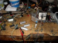
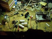
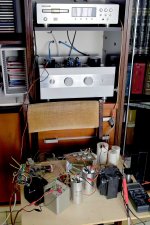
First Heat sink Test
Thisi s the first heat sink I received. It measures approximatly 2.5" X 1.5" with 0.7" deep fins that are 0.80" thick. There are eight fins.
I am using a Triad F7-12 transformer (12.6V Ct @ 4A) with a IR 12CTQ030 rectifier. (dual 6A 30V Schotty diodes) with 4 X 4400uF 35V capacitors for filtering.
Input to the Coleman type regulator is 8.28V.
I'm using a .33R sense resistor with 0.823V across it. With 2.5V on the 2A3 (bad tube with a good filament I use for testing) I'm left with about 4.96 volts across the two TIP122s.
At 2.5A that is roughly 12.4W dissipation.
Temp at the case of the current sink is 144F at an ambient of 70F for a 74F rise (about 41C). It looks like a 3.3C/W heat sink.
WIth a Tjc of 1.92 C/W and even distribution of the load between the two transistors, that works out to a junction to case rise of about 11.9C. Added to the 41C , and adding 21C ambinet I arrive at a junction temp of only73.9C which is only half of the specified 150C, so it should have a good reliability.
So it looks like a pretty small heat sink may be acceptable for a single 2A3 tube. Even if the voltage in is increased to 10.28V, the additional dissipation would only be 2.5W per transistor for a rise to about 8.3C for a die temp of 82.2C.
If the heat sink were mounted on a chassis and bolted to it, with vent holes in the chassis, the temp rise would be even less.
Attachments
Good work!
I like to see the heatsink at a target maximum temperature of about 65-70 deg C - using the FP insulated transistor packages. With standard TO220, you can go a little higher.
This way, you have some margin when the power is applied to a cold filament after a power outage - ie the voltage across the filament is lower, and this extra voltage is applied to Q5. Then again, the Coleman Regulator applies the positive voltage on a slow ramp, so the effect is very small in practice.
Enjoy the 2A3 sound!
I'm using the standard TO-220 with a mica insulator and Dow Corning 340 heat sink compound. I have to use silicon insulators for HV because the hole for a screw in the mica insulators is way too large and I've had shorts with them.
Mica has a lower theta (0.5C/W) than the silicon pads (0.89C/W), but is more prone to damage and shorts. I'd like to try the ceramic insulators, but the TO-220 ones I've seen look way too thick compared to the ones we use at work, so I'm not too confident in them.
It takes quite a few seconds for the voltage to come up. Could I drop C1 to 47uF or even 22uF and speed it up a bit without risk?
Laying flat witht he fins up and a cardboard skirt to control air flow I only saw an additional 5C rise in temp. Mounted on an Al chassis, I expect even lower temp rise.
The slow ramp capacitor helps with the cold filament situation - the current rises slowly, even when the voltage across the filament is very low.
The aim is to keep the rise time-constant similar to the thermal time-constant of the filament - or longer.
But 47uF should be fine, if preferred.
The aim is to keep the rise time-constant similar to the thermal time-constant of the filament - or longer.
But 47uF should be fine, if preferred.
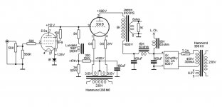
My 300B Loftin White.
Hi Rod.
I already wrote to you an email message yesterday by the Italian forum "Audiofaidate" asking if you can still sell two assembled units of your heater regulator for my 300B Loftin White (attached) and how I can pay them.
I just registered myself in this forum to obtain direct information from the attachments in your posts.
Just one channel (connected to my old modified Marantz SA8400)"lying" on a chair, is already optimally driving one of my 94db speakers.
-The "irons" have been chosen for a low impedance supply (63 ohm chokes, 37ohm-450Vac).
-All capacitors 100uF MKP 450Vac.
-High anode load impedance (5K) for lower distortion and high DF (about 5).
Just one question: in some of your attachments I see the positive of the heater go to ground, while in others the negative... which one?
Any suggestion on my layout is welcome!
Have a nice day,
Italo
Attachments
Hi Italo,
I have sent you a "private message" with details for 300B regulators.
The Filament + terminal usually gives the best sound, but you can try -ve - but please take care that the bias voltage is higher, when using -ve side.
Some circuits are using "Filament Bias", and this time you have no choice - the -ve side must be used.
Hi Rod.
Thanks a lot!
Yes, I saw it.I have sent you a "private message" with details for 300B regulators.
Thanks a lot!
OK... I'll try both!The Filament + terminal usually gives the best sound, but you can try -ve....
- Home
- Amplifiers
- Tubes / Valves
- New DHT heater