As Zen Mod suggests - that way the IT1 MAX and RMS values show you the peak charge currents (switching diode stress and noise coupling back through the transformer) without the influence of the initial inrush to charge the capacitors.
That will be more informative.
Rod,
Still following this thread - My parallel push pull 300B monoblocks will happen - eventually.
Pliton Power Tranny, PS Choke, Output Tranny, all the 300Bs (Electoharmonix) and custom chassis, Guido's Bias Servo Boards are just sitting on the shelf waiting for me to stop sitting on my butt.
Do you have a recommemndation for heating 4 off 300B per monoblock, parallel push pull connected.
Cheers,
Ian
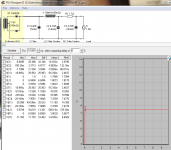
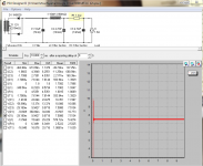
OK, updated sims after a 5 sec delay
It1 max went from 8A to 3A
Hi Randy,
That's the advantage with choke input.
The value of C3 can now be increased to 10000uF or even more, without affecting the peak current too much. But the output ripple voltage will decrease substantially.
As Zen Mod suggests - that way the IT1 MAX and RMS values show you the peak charge currents (switching diode stress and noise coupling back through the transformer) without the influence of the initial inrush to charge the capacitors.
That will be more informative.
Rod,
Still following this thread - My parallel push pull 300B monoblocks will happen - eventually.
Pliton Power Tranny, PS Choke, Output Tranny, all the 300Bs (Electoharmonix) and custom chassis, Guido's Bias Servo Boards are just sitting on the shelf waiting for me to stop sitting on my butt.
Do you have a recommemndation for heating 4 off 300B per monoblock, parallel push pull connected.
Cheers,
Ian
hi Ian,
Paralleled 300B filaments can certainly be heated with a single 2.7A regulator. You can even run the other PP half with the same regulator (by connecting in series), but for this to succeed, the PP pair must run fixed bias, and have the ability to adjust the grid voltage separately for each PP-half. You'll need a 5V difference between each grid voltage. (It's certainly more straightforward to use separate regulators for each PP half.
If you're using Guido's bias module, you must be able to connect it so that the anode-current for each PP half is sensed separately, and issues a separate grid voltage. Maybe Guido can comment on whether this is possible?
Rod,
Thanks - Guido's modules, 4 channels, each channel has a 10 Ohm to 0V sense resistor to go into the tube cathode circuit and a servo to set grid bias to achieve a particular idle current, set by a common (to all four channels) reference. So I need to accommodate a separate 10 Ohm resistor to 0V for each tube.
I am also trying to get my head around the late Allen Wright's idea of running the push pull pair in pure class A with a current source between the common filaments back to 0V. I think you could still get losses back thru' the filament power circuit but the forced balance operation may compensate for that - thoughts?
Cheers,
Ian
hi Ian,
The filament transformer, and its rectifier/capacitor/filter network must float from ground (the negative side of B+, that is). This prevents any current (dc or music) from running back up the filament supply.
In this case the only connexion to the B+ supply is the common CCS ground that you mentioned. There shouldn't be any losses involved with this arrangement - all should be well.
Do I use a humpot with this DHT heater or not?
hi Åke,
A hum pot is used to effectively null the hum and noise currents found in every AC or badly-implemented DC heating circuit.
With the Coleman Regulator solution, the noise currents are completely removed, so there is no need for a hum pot. Actually, it will degrade the sound - so please remove it!
hi Ian,
Paralleled 300B filaments can certainly be heated with a single 2.7A regulator. You can even run the other PP half with the same regulator (by connecting in series), but for this to succeed, the PP pair must run fixed bias, and have the ability to adjust the grid voltage separately for each PP-half. You'll need a 5V difference between each grid voltage. (It's certainly more straightforward to use separate regulators for each PP half.
If you're using Guido's bias module, you must be able to connect it so that the anode-current for each PP half is sensed separately, and issues a separate grid voltage. Maybe Guido can comment on whether this is possible?
I have bad experiences with paralleling filaments. At best one feeds each filament with its own filament supply. Once all is separated, the current sense is also feasible. When building PP amp make sure to set it up symmetrical in terms of filament connection, and the filament to ground connection.
I've seen too many (Chinese) tube amps with mixups - no good for the sound.
best
hi Åke,
A hum pot is used to effectively null the hum and noise currents found in every AC or badly-implemented DC heating circuit.
With the Coleman Regulator solution, the noise currents are completely removed, so there is no need for a hum pot. Actually, it will degrade the sound - so please remove it!
Ok,how do I connect the cathode resistor?To one pole or to both via 100 ohms resistor?
It´s a "free lunch so the filament mus be floating.
Åke, if you are using Coleman Regulators, please connect the cathode resistor to the positive (Filament+) terminal.
The instructions are found in the the PDF document ANdht01, page 10. There's a connexion drawing and directions.
please send some email, if you don't have it now.
The instructions are found in the the PDF document ANdht01, page 10. There's a connexion drawing and directions.
please send some email, if you don't have it now.
One more question can/should I use the 40uF elyt between the B+ and the cathode of 6B4G when using the coleman regualtor?
Yes, the "Monkey" capacitor can be used.
The Coleman Regulator does not care about the cathode voltage, because the raw Filament Supply is not connected to ground.
The only limits on the allowed cathode voltage are:
- the insulation of the filament transformer's secondary winding (winding-to-core); should be >1kV
- the plastic transistor insulation: >1kV for plastic transistors, or Mica insulators, if held by a clip (don't use screws for high voltage).
Everything should be fine, for any practical value of cathode voltage.
.
Heatsink size when driving 2A3
I wish to use the Coleman regulator with a 2A3 tube.
My filtered voltage to the regulator is 8.5V
That leaves 8.5-2.5 = 6V at 2.5A = 15W I need to get rid of.
40°C is a reasonable rise for good reliability, so I need a heat sink with theta sink-ambient of about 2.7°C/W.
The problem is that the heat sinks on ebay don't list theta. I've looked at heat sink material from manufacturers and it looks like a heat sink 60cm^2 with 20mm fins is about the minimum that would work.
Is anyone using heat sinks (as opposed to bolting the transistors to the chassis) that can confirm or refute this?
It's about 12W through the heatsink interface, at 8.5V and 2.5A. The other couple of Watts radiate from the sense resistors and PCB radiation of the transistor dissipation. The 2A3 regulator works down to 7.5V, so if your mains supply tolerance permits, a small extra dropper resistor can ease the power a little more.
Mouser 567-517-95AB is the 517-95AB made by Wakefield. It can manage 11W for a 60 deg C rise, and is 58 x 61 x 24mm (very similar to the size you have seen). Wakefield also claims 2.0 K/W - but this is with a "300ft/min" forced convection. We must beware of headline specs, as usual.
http://www.mouser.com/ds/2/433/wakefield pwr semi heatsink-202130.pdf
So, a slightly bigger sink is needed, or mount it on some chassis with the sink on the other side; or use two of this approximate size (ebay) heatsinks mounted on a spreader bar of Alu (Alu bar is usually low cost on ebay, and a 3 .. 5mm thick stick of Alu makes a fine heatsink mounting interface)
UK vendor example:
Aluminium Flat Bar / Plate widths from 1" to 1.5" many thicknesses and lengths | eBay
30mm x 150mm (or more) and 5mm thick is good value.
Another option: set up a high quality/low noise (eg Sanyo Denki) 24V fan, and supply it with the 8.5V raw dc. Quite a bit of cooling, very low noise. For instance, the 9S0924M4011 yields only 22dBA at full voltage, and you might even get away with using the 12V version and feeding in 8.5V. This kind of cooling can be very kind to any transformers or capacitors in the chassis, too.
9S0924M4011 Sanyo Denki | Mouser
- Home
- Amplifiers
- Tubes / Valves
- New DHT heater