Hi Disco,
No it's not novel. As you mention it has been done in many implementations during many, many years...
The thing is to find/use types that are suitable for the application. For instance in the Tram II preamp this will mean types that are at least rated at 2,5A continous current and has low rdc on around 0.1 - 0.2 ohm. Not many of those around, and the possible improvement over resistors is minimal because the induction will be relatively small.
I will try to wind some low rdc aircore coils to test with (similar to DHTrob that you are mentioning).
Last edited:
Gyrator compatibility with other CCS?
Hi. I already have voltage controlled current sink (VCCS) installed and working in my amp. Is it possible to use the gyrator only in the positive leg to gain benefit? The VCCS I have uses a FET in the negative leg. I'm not sure what type of FET. The positive leg is direct to the filter caps then a diode bridge. So I believe there would be benefit in using the gyrator in the positive leg. That's why I'm asking. I believe the VCCS works quite well sonically so I'd rather keep them if possible.
Thanks,
Adrien.
I should restate the question. Is the gyrator dependent on the CCS or can it be used separately? I have tried to find this information in this long thread. I believe it can but there may be something I missed.
Thanks,
Adrien.
These are two completely independent circuits
operate separately
in this case are in series
separated by a filament that is the load resistance
I decided to try Rod's regulators to replace my voltage controlled current sink regulators. Last weekend I did a very quick test. My test filament power supply had very long wiring throughout, a cheap bridge diode, a cheap filter cap and a single bobbin EI transformer with a variac. My A+B test was to use Rod's regulator on one DHT 3C24 input tube only and listening to one of the stereo channels. I can report positive results. So much so that I will be redesigning my filament supply and using Rod's regulators for all 4 tubes. It's a major change so I wouldn't do it if the improvement was minor. If I was to try and describe the improvement, it is as though a veil was removed from the speaker. Micro details become clearer and more audible. There is more tone making the instruments more real like. I listened to orchestra violin concertos music on vinyl.
A BIG thank you to Rod for sharing his regulator with us.
Adrien.
A BIG thank you to Rod for sharing his regulator with us.
Adrien.
I'm trying to figure out what the heatsink size is for running 2 regulators, each dissipating around 20W for a total of 40W. (5V*4A per regulator). I added a bit of V for headroom. If I use a heatsink that is about 1 deg C/W I calculate a junction temp of around 125 deg C. This is using 3 deg C for junction to mica to heatsink and 25 deg C ambient. Is this safe enough or do I need a bigger heatsink?
Thanks,
Adrien.
Thanks,
Adrien.
A 1 K/W heatsink will give a 40 deg. C rise for 40W, giving a heatsink temperature of 65 deg C.
This heatsink temperature is safe for all versions of the regulator, so it is OK, provided the heatsink can reach its full performance, and that 25 deg C is the real maximum ambient temperature - which means the heatsink must be on an external surface of the chassis.
But keep in mind that the heatsink is designed to be able to circulate air to meet its 1K/W rating - so it should be mounted with fins vertically oriented, and without obstruction to air flow.
When the Regulator is running on the heatsink, the temperature can be checked, to ensure that it is below 70 deg. C.
If you have other metallic chassis parts near to the heatsink, making a good mechanical connexion between the heatsink and the chassis will improve the cooling. In practice, 2mm - 4mm thick Alu top plates are very efficient at cooling.
I hope they are sounding good!
It's possible that a switching converter could be used as a pre-regulator for my Filament Regulators - but careful precautions are advisable.
I assume we are talking about the "off-line" (mains to dc low-voltage) converters.
The first caution is to measure the leakage current from the low-voltage output to safety earth (Ground). Some converters, including the expensive and well-certified FRIWO units I specified for my Handheld PC design work - have very high levels of leakage. It seems to be caused by high primary-to-secondary capacitance. Intentionally-placed capacitors, even.
With Cathode bias, or Filament-bias applications, leakage current is a disaster. The B+ return (System Ground) in our amps must be connected to safety earth (one way or another), and so any leakage current from the raw supply for the filaments will run through the cathode/filament-bias resistors. Leakage current of this kind is very noisy, and the outcome will be highly degraded sound.
Measure the leakage. Anything more than a few microamperes (ac) is probably too much. If you have a scope, connect the output of the converter to safety earth via a 100K resistor, and scope out the resistor, to assess the noise current.
With fixed bias amps, our cathode is at Ground potential. But the noise current will still run along the same conductors as our anode (music) signal current. check out the bandwidth of the noise. Is the impedance of the Ground circuit zero over this bandwidth? If not, noise injection is certain.
On the other hand, you may find a converter that does not leak. Maybe a salvaged Medical equipment converter?
For example, a medical PC 400W supply leaks 90uA:
ATX PC Power Supply Features 90 uA Low Leakage Current at 264 VAC
This is not good enough, in my view.
A Bear supply leaks 5uA:
Custom medical power supplies with ultra-low leakage current to be used in heart-connected instruments
This may just about be good enough. But it certainly illustrates the challenge.
Meanwhile, a good EI transformer has about 50pF interwinding capacitance, and about 100pF winding to Core. In this case, a 10V 50Hz common-mode pulse will give a peak current of 150nA, or 100uA if the frequency is 50kHz.
I have measured Toroidal transformers with 1000pF or higher of interwinding capacitance, and usually the core has no option but to float. The leakage current with these increases in proportion to the leakage capacitance - substantially worse than the EI.
Overall, I think the EI trafo, plus schottky rectifiers is the safest solution. But in this application measuring is quite sufficient to verify a converter.
In all cases, mount a converter at a distance from the signal wiring, to keep switching noise out of the amp.
Hi
I am looking at building a DHT amp using the Coleman Filament Regulators.
I plan to make this amp using the Tubelabs SE (TSE) board, ordered one the other day.
I would like to make the amp work with both 300b and 45 tubes, hopefully without too much effort to switch between the two.
With the TSE, I can change the bias for each tube. B+ of may 320V.
So I just need to worry about the different heater voltages for these tubes.
It looks like the regs are adjustable, so I can adjust them for either tube.
I think I would need to use a 9V, 50VA tranny per the 300b requirement, so the input voltage will be high when using a 45, so I will need large enough heat sinks go compensate for the higher input voltage.
Does this sound reasonable?
Did I miss anything?
Any other comments?
As always, any advice is appreciated.
Randy
hi Randy,
the Coleman Regulators can be adjusted for current, and the current-range can be set up for 300B (adjusts 1.1 - 1.4A) or 45 (1.4 - 1.7A) by adding one resistor for the 45.
For the raw dc supply, a transformer with a 7.5V secondary (for 45) or a 9V rms (for 300B) is needed - or the 9V rms winding can be used for both, if an extra 1.5 ohm of series resistance is added to the raw dc while the 45 is in use.
Lots of application information available for filament heating of these DHTs - please send me some email to have copies.
Hi Rod
Thanks for the help.
I want to use the same tranny for both tubes, so I will use a 9v tx, and add a resistor for 45 tubes.
Is this OK for the tranny?
Hammond 9v 166m18 tx
I will send a PM about the 300b and 45 app notes.
Thanks
Randy
Thanks for the help.
I want to use the same tranny for both tubes, so I will use a 9v tx, and add a resistor for 45 tubes.
Is this OK for the tranny?
Hammond 9v 166m18 tx
I will send a PM about the 300b and 45 app notes.
Thanks
Randy
So I received my regs in the mail yesterday, have been figuring out what I need to buy for the raw PS.
Wondering if people have an opinion of CRC versus CLC for this? I can make the space for an inductor, if it improves performance.
I have a balanced power conditioner from BPT that will most likely be feeding this amp.
Randy
Wondering if people have an opinion of CRC versus CLC for this? I can make the space for an inductor, if it improves performance.
I have a balanced power conditioner from BPT that will most likely be feeding this amp.
Randy
Hi Randy,
If you are using a power conditioner, I would hope that common-mode noise will be rejected better than before.
The Coleman Regulator does not usually need extra (differential-mode) ripple-rejection, so CLC will not make much difference, except maybe on very low level stages in phono amps.
However, a plain LC filter has scope to improve the system overall, not due to any effect on the filament supply, but because the choke-input will calm down the peak recharge-pulse currents into the rectifier's capacitor. High recharge pulses can pollute the local mains, if the local network impedance is unfavourable (makes little difference for me, but will be supply dependent).
In practice, a CLC made up of (eg) 10uF MKP at the rectifier, a choke of 10mH, 160mOhm, 5A (Hammond 159ZJ) and 10000uF/35V will be very quiet, and take the recharge current right down.
PSUD2 must be used to design the raw supply, and choose the right transformer.
I usually have some example PSUD2 files for choke-input supplies, if you need them.
I don't think that any of this amounts to major effects - but some folks like to build things the absolute best way possible, and if this is you, a choke-input raw supply is worth a look.
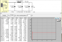
Here is the simulation I did in PSUD for a 45.
But, to complicate things, I would like to be able to use either 300b or 45's in the same amp.
I think if I change R1 to 1 ohm, should give around 10v at the 300b load.
BTW, I would rather "overdesign" and not have to worry that I could make it better by adding a LC later.
But, to complicate things, I would like to be able to use either 300b or 45's in the same amp.
I think if I change R1 to 1 ohm, should give around 10v at the 300b load.
BTW, I would rather "overdesign" and not have to worry that I could make it better by adding a LC later.
Attachments
Hi Randy,
For choke-input version please try C1=10uF, rather than 10mF in the PSUD2. The transformer voltage will need to be increased to about 12V, but with only about 2.5A rms capacity.
Comparing the peak currents in (eg IT1 or ID1) will show the potential for what choke-input can offer.
For choke-input version please try C1=10uF, rather than 10mF in the PSUD2. The transformer voltage will need to be increased to about 12V, but with only about 2.5A rms capacity.
Comparing the peak currents in (eg IT1 or ID1) will show the potential for what choke-input can offer.
- Home
- Amplifiers
- Tubes / Valves
- New DHT heater