Thanks Charlie, I got a reply from them:
Cost of spray is £30.98
We have stock for immediate shipping - next day if ordered by 3pm. We accept cards. Please note that carriage is £15 (haz) and we operate a minimum order value of £50.
Permanent Static Dissipative Coating, Anti-Static Coating - Techspray 1756 Licron Crystal from INTERTRONICS (Carriage is for local delivery.)
Hi,
wondered why You chose stranded wire.
I doubt that You can keep up the constant pull longtime and chances are that certain single strands inside the wire will crack.
I´d opted for single strand wires like the H05VU or the bigger brother H07VU (the wire Audiostatic use, manufactured by Pope, Venloe).
Single stranded wire requires some effort in straightening, but requires less support and no constant mechanical pull when mounted.
When You design a wire stator with a frame and ladder structure like the Audiostatics, the frame itself could be used as spacer.
The difference in thickness the wire and of the frame plus a thin glue joint then defines the d/s-distance.
Advantage here that a very thin glue joint or tape is required.
A thin tape takes the strong shearing forces much better than a thicker foam tape.
You may then use cheaper carpet tape or similar.
A frame may be made from strips of PVC, Trespa, Acrylic glas or similar.
All materials which are easy to source and quite cheap.
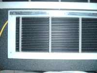
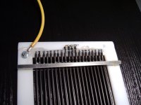
Attached are some pics of one of my old early wire panels to show some details of frame/stator construction and diaphragm contacting.
First pic shows the frame made from strips of a plastic ... think it was unfilled PVC.
The top an bottom parts shaped like a T to exactly define the inner width and to cope with the horizontal and vertical pulling forces that act upon the frame.
A simple machine screw bolted through a layer of household aluminum foil (yup!) and the frame acts as diaphragm contact strip.
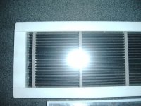
Second pic shows the second stator with mounted membrane.
Tape used here was a Tesa carpet tape.
The frame strip width was chosen wide enough that there´s enough glue joint area to cope wih the membrane´s pulling forces.
The tape is around 1-2/10s of a mm thick and should reach to the inner edge of the frame.
Be aware that a sharp inner edge of the frame may actually cut the membrane.
The thin tape provides for enough distance to keep the membrane safe.
In a larger panel I also glued some foam to the inner edges to provide for a bit of damping for the standing waves that develop over the membrane.
As additional dampers small strips of foam are glued below each ladder-step.
Similar to Audiostatic and most other wire stator manufacturers You may work with silicone drops instead.
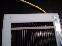
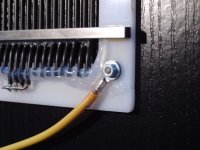
The ladder can be seen in pics 4 and 5, made from 5x5mm steel rods, cut to length.
Audiostatic used shallow quadratically shaped 10x10mm aluminum bars.
Both materials are easy to source in any diy-shop.
The metal bars are optically quite pleasing, but a insulative materal would be advantageous technically.
You may use the same material as for the frame, if You hide the panel later under a piece of cloth, or something like clear acrylics, if You like Your panels ´visually open´
The stator´s middle wires are connected to the transformer the same side as the Membrane bias contact.
The outer parts are segmented with resistors at the other end of the stator.
To get the wires perfectly straight You may build Yourself a stretching jig or stretch each wire its own.
The latter doesn´t require a jig and gives most perfect straightness, but is time and labour consuming.
Wire used here was a H0/VU which is used as standard household wiring.
As such You may source it at any corner at lowest cost.
Open HV-leading parts like the membrane connector or the wire ends are isolated with blobs of silicon.
The membrane coating is my glue formula which You can find in other threads here at DIYaudio.
The panel must be around 20 years by now and is still in perfect working condition.
IIrc the cost for the pair of panels was less than 50Bucks wo electronics.
It was designed as a mid-high panel with aintended frequency range of 600Hz->20kHz.
dim: 3x80cm, frame strips 20mm wide 4mm thick, wire H07VU (dia: 3.2mm) --> d/s: 1.0mm (w. tape).
Nowadays I´d choose thinner wire like H05VU for so small d/s values.
The measurements were taken nearfield.
The amplitude response (nearfield) shows the high-Q base resonance of the membrane at ~110Hz and a rise towards the upper end due to the undampened transformer leakage resonance (a series resistor at the trannies primary will counter that resonance and lifts the impedance to more amplifier-friendly values).
BTW: Transformers used here were a quad of cheap 10VA EI-core power trannies with 230V/6V") .
.
Within the working range amplitude and phase resonse are sufficiently linear.
The requirement for ~5 octaves of useable bandwidth is clearly met.
Second measurement shows the nearfield Step response.
Though a CSD shows minor issues at 1.7kHz and 3.4kHz (coincidence of standing wave due to the inner width of the frame (10cm), the Step response is as close to ideal as one could wish for, especially regarding the cheap components and low price tag of this transducer.
The crossing into the negative at 2ms is a artifact of the high-Q base resonance, visible for all Q values >0.707.
The slight peaky behaviour at 0ms is due to the tranny-leakage-related amplitude rise.
Highpass filtered at 600-800Hz and depeaked with a resistor, the Step is even closer to textbook ideal.
This is just to show, that even with easy to source cheap materials You can produce a wide bandwidth ESL-transducer at Your home that not only sounds spectacular but also measures very well.
I´d like to quote J.L.Picard: Engage!
jauu
Calvin
wondered why You chose stranded wire.
I doubt that You can keep up the constant pull longtime and chances are that certain single strands inside the wire will crack.
I´d opted for single strand wires like the H05VU or the bigger brother H07VU (the wire Audiostatic use, manufactured by Pope, Venloe).
Single stranded wire requires some effort in straightening, but requires less support and no constant mechanical pull when mounted.
When You design a wire stator with a frame and ladder structure like the Audiostatics, the frame itself could be used as spacer.
The difference in thickness the wire and of the frame plus a thin glue joint then defines the d/s-distance.
Advantage here that a very thin glue joint or tape is required.
A thin tape takes the strong shearing forces much better than a thicker foam tape.
You may then use cheaper carpet tape or similar.
A frame may be made from strips of PVC, Trespa, Acrylic glas or similar.
All materials which are easy to source and quite cheap.
Attached are some pics of one of my old early wire panels to show some details of frame/stator construction and diaphragm contacting.
First pic shows the frame made from strips of a plastic ... think it was unfilled PVC.
The top an bottom parts shaped like a T to exactly define the inner width and to cope with the horizontal and vertical pulling forces that act upon the frame.
A simple machine screw bolted through a layer of household aluminum foil (yup!) and the frame acts as diaphragm contact strip.
Second pic shows the second stator with mounted membrane.
Tape used here was a Tesa carpet tape.
The frame strip width was chosen wide enough that there´s enough glue joint area to cope wih the membrane´s pulling forces.
The tape is around 1-2/10s of a mm thick and should reach to the inner edge of the frame.
Be aware that a sharp inner edge of the frame may actually cut the membrane.
The thin tape provides for enough distance to keep the membrane safe.
In a larger panel I also glued some foam to the inner edges to provide for a bit of damping for the standing waves that develop over the membrane.
As additional dampers small strips of foam are glued below each ladder-step.
Similar to Audiostatic and most other wire stator manufacturers You may work with silicone drops instead.
The ladder can be seen in pics 4 and 5, made from 5x5mm steel rods, cut to length.
Audiostatic used shallow quadratically shaped 10x10mm aluminum bars.
Both materials are easy to source in any diy-shop.
The metal bars are optically quite pleasing, but a insulative materal would be advantageous technically.
You may use the same material as for the frame, if You hide the panel later under a piece of cloth, or something like clear acrylics, if You like Your panels ´visually open´
The stator´s middle wires are connected to the transformer the same side as the Membrane bias contact.
The outer parts are segmented with resistors at the other end of the stator.
To get the wires perfectly straight You may build Yourself a stretching jig or stretch each wire its own.
The latter doesn´t require a jig and gives most perfect straightness, but is time and labour consuming.
Wire used here was a H0/VU which is used as standard household wiring.
As such You may source it at any corner at lowest cost.
Open HV-leading parts like the membrane connector or the wire ends are isolated with blobs of silicon.
The membrane coating is my glue formula which You can find in other threads here at DIYaudio.
The panel must be around 20 years by now and is still in perfect working condition.
IIrc the cost for the pair of panels was less than 50Bucks wo electronics.
It was designed as a mid-high panel with aintended frequency range of 600Hz->20kHz.
dim: 3x80cm, frame strips 20mm wide 4mm thick, wire H07VU (dia: 3.2mm) --> d/s: 1.0mm (w. tape).
Nowadays I´d choose thinner wire like H05VU for so small d/s values.
The measurements were taken nearfield.
The amplitude response (nearfield) shows the high-Q base resonance of the membrane at ~110Hz and a rise towards the upper end due to the undampened transformer leakage resonance (a series resistor at the trannies primary will counter that resonance and lifts the impedance to more amplifier-friendly values).
BTW: Transformers used here were a quad of cheap 10VA EI-core power trannies with 230V/6V
.Within the working range amplitude and phase resonse are sufficiently linear.
The requirement for ~5 octaves of useable bandwidth is clearly met.
Second measurement shows the nearfield Step response.
Though a CSD shows minor issues at 1.7kHz and 3.4kHz (coincidence of standing wave due to the inner width of the frame (10cm), the Step response is as close to ideal as one could wish for, especially regarding the cheap components and low price tag of this transducer.
The crossing into the negative at 2ms is a artifact of the high-Q base resonance, visible for all Q values >0.707.
The slight peaky behaviour at 0ms is due to the tranny-leakage-related amplitude rise.
Highpass filtered at 600-800Hz and depeaked with a resistor, the Step is even closer to textbook ideal.
This is just to show, that even with easy to source cheap materials You can produce a wide bandwidth ESL-transducer at Your home that not only sounds spectacular but also measures very well.
I´d like to quote J.L.Picard: Engage!
jauu
Calvin
Attachments
Last edited:
Cheap Chinese power toroids like these work great but I've learned that their winding polarities don't always match the phasing dots on their data sheet (or my schematic).
One of the four VTX transformers I tested had its red & black leads reversed, such that one of its 6v windings was out of phase. So, when I assembled the transformer pair their windings cancelled and I got no sound. Once I identified the reversed polarity and swapped the leads, they worked fine and sounded fantastic.
I checked the winding polarities by applying 115VAC into the 230 volt winding; and then measuring the voltages out of the 6 volt windings using a DVM and jumper wire, as shown here: Test Procedure
Good luck with your project!
Last edited:
I second Charlie's advice. I had the same problem on my first build and it took the sages here to figure out what the problem was. This was with the Antec transformers. It is an easy mistake to make when winding, a little more difficult to figure out later.
Hi Ken,
Yes, I remember that now. I think it was your small perf metal panels, as I recall. I had not seen your Segmented ESL project until just now when I clicked on your link. FANTASTIC JOB! Nice write up too.
I almost wish I hadn't seen your project page because it started wheels turning in my old skull here... and it's not like I have the bucks to indulge this psychosis anymore!
some info from Electrostaten Draadstator ESL regarding wire choices
Copper solid core should be discouraged. This wire is too stiff to be easy to process and exhibits at lower frequencies pronounced resonances.
for such elements for the middle / high we can best take a thinner litz wire in connection with the achievement of a homogeneous field distribution in a smaller membrane width. For example, a thickness of 0.15 mm 2 , consisting of 18 wires of 0.1 mm and having an outer diameter of 1.15 mm.
the thread is available in rolls of 100 m (0.75 mm 2 ), and reels of 200 m (0.15 mm 2 ). It is cheaper to buy. Thread per 100 or 200 meters
Hi,
if single stranded wire were too stiff to process, how come that a couple of companies and many DIYers manage to get them straight without issues?
Yes, it takes effort to straighten the wires, either by manufacturing a stretching jig and stretching all wires at once, or by stretching each wire one by one.
Using a stretching jig, the required time for stretching and mounting the wires is low, just a couple of minutes.
If You want to get something to resonate as hell, than take a string and put a constant pull on it.
Every plugging or string instrument, be it a guitar be it a violin, is a perfect proof.
Replace the guitar string by a straightened pvc coated copper wire and listen to that sound.
Release the pull on the string and the sensitivity to resonate decreases.
If you wanted to use stranded wire then You would need to support the wire, such that the free distance remains very small, to achieve a resonance so high in frequency, that it is easy to dampen and possibly lying in the ultrasonic range.
Acoustat used the crates as support to the wire at every couple of millimeters.
Then, stretched stranded wire may behave acoustically inert.
A Audiostatic-alike ladder structure that spans around 100mm of free distance requires stiff single stranded wires, as soft multistranded wires would resonate like in a violin.
As the wires need to be fixed to the support structure, a ladder structure is less work and more DIY friendly than a crate structure.
And last not least, the cost of a standard industry mass product like the H07VU/H05VU is certainly lower than a multistrand wire.
Simply think of how many more production steps are required for a multistrand wire and how many more tons of single stranded wires are produced each day.
Man, when I read that linked stuff years ago, I thought: "Rubbish!"
And that is exactly the same I think today.
jauu
Calvin
In one of my earlier builds, I used .062" TIG rod, which is a thin steel rod which spanned about 12" (30cm). It acted like a harp with terrible ringing, but that is very different than standard copper, which does not have the stiffness that steel does. I have to agree with Calvin - stranded wire under tension has to be far more prone to resonance than single core copper which is not taut.
In my most recent build, I used far thinner TIG rod, but supported it every 1/2" (1.3cm) using egg crate and have none of the mentioned ringing problems.
In my most recent build, I used far thinner TIG rod, but supported it every 1/2" (1.3cm) using egg crate and have none of the mentioned ringing problems.
If I were to build a panel with larger rods (say .090 or .125 dia) that may be a viable solution. But may ultimately be unnecessary.
I chose much finer rods (.035) spaced close together. Using shrink wrap on these would chew up all of the available space between rods.
Corona effects are greatest when there are pointy bits. Since the rods have their curved profile to the diaphragm, corona effects are far reduced. Having a very thick, effective insulation is less important than in perforated panels. A simple paint job was sufficient insulation, even with the small radius I had with the 035 rods.
Hi,
The one and only circumstance under which the above could be tolerable is a isolated non-touchable mounting of the stators behind earthed screens.
If there´s the slightest chance that the stators are touchable the above is rightout dangerous!
Touching Stators may be lethal!
So please don´t talk or believe in such dangerous ****!!
You´d better know what You´re doing!
Just because a round wire has no sharp points doesn´t mean that You may fudge with insulating thickness unsensibly.
Typically metal sheet stators show sharper edges and smaller whole radii which inher the problem of high field strength and lower insulation thickness at the same (neuralgic) spots, yes.
On the other hand are the required driving voltages typically alot lower than those for wire stators.
If Your insulation layer is too thin or not free of pinholes the danger of flashover and electrical shock is present, regardless of the construction of the conductor.
Keep also in mind that the wires (PVC-copper) are not specced by far for voltage levels that may occur easily and regularly with Wire stators.
Keep also in mind that insulations should be specced for pinhole freeness or at least on the number of possible pinholes per length of wire (see for example specs of Magnet wire).
jauu
Calvin
ps. NASA´s greatest catastrophies occurred when safety issues lost the top position on their list of attention, but became ´business as usual´.
Having a very thick, effective insulation is less important than in perforated panels.
The one and only circumstance under which the above could be tolerable is a isolated non-touchable mounting of the stators behind earthed screens.
If there´s the slightest chance that the stators are touchable the above is rightout dangerous!
Touching Stators may be lethal!
So please don´t talk or believe in such dangerous ****!!
You´d better know what You´re doing!
Just because a round wire has no sharp points doesn´t mean that You may fudge with insulating thickness unsensibly.
Typically metal sheet stators show sharper edges and smaller whole radii which inher the problem of high field strength and lower insulation thickness at the same (neuralgic) spots, yes.
On the other hand are the required driving voltages typically alot lower than those for wire stators.
If Your insulation layer is too thin or not free of pinholes the danger of flashover and electrical shock is present, regardless of the construction of the conductor.
Keep also in mind that the wires (PVC-copper) are not specced by far for voltage levels that may occur easily and regularly with Wire stators.
Keep also in mind that insulations should be specced for pinhole freeness or at least on the number of possible pinholes per length of wire (see for example specs of Magnet wire).
jauu
Calvin
ps. NASA´s greatest catastrophies occurred when safety issues lost the top position on their list of attention, but became ´business as usual´.
Remember that even though the stators are insulated and you maybe to touch them with the bias voltage on, they are capacitors and if you were to touch both stator's at the same time while they are operating with a signal you will feel the full voltage of the signal with the Bias Voltage added to it !!!!
This across the chest can/will be LETHAL.
The last time I got nailed by 10Kv of my Bias supply was with just one hand and it did set me back a bit!!!!
I am very lucky to be here typing this warning!!!!
Never use both hands while working on them while they are powered up!!!!
EVER!!!!
jer
This across the chest can/will be LETHAL.
The last time I got nailed by 10Kv of my Bias supply was with just one hand and it did set me back a bit!!!!
I am very lucky to be here typing this warning!!!!
Never use both hands while working on them while they are powered up!!!!
EVER!!!!
jer
I'm glad I only build full range planars, just as good or better than ESL's, and a lot safer and easier to replace diaphragms.
You don't know what you're missing, Henry.
- Status
- This old topic is closed. If you want to reopen this topic, contact a moderator using the "Report Post" button.
- Home
- Loudspeakers
- Planars & Exotics
- New build questions