The TIG rod I used was 0.035" (about 1/29"), much thinner than 1/8" rod. I had made a couple of test versions of the stators with 1/8 and 1/16", but liked the evenness of the 35mil rod (it seemed to me to more closely approximate a flat sheet). Since these were glued to the egg crate every 1/2" there was no problem with support. I used 1/2-13 allthread to get the spacing just right which gave me 13 rods per inch. It may seem very tedious to use such fine rod, but in the end, it only took me about 1-1/2 hours per panel to align and glue the rod.
I did use some 1/8" rod on the back of the panel when using the thinner/cheaper egg crate to give it a little more stiffness.
As for insulating the TIG, that has not been a problem for me. On the test version I did with 1/16" rod, I had one primer coat, and 2 top coats of rustoleum spray paint. I had a 1/16" d/s. I was able to crank the bias up to almost 7KV before I had significant corona. I did not do a breakdown test on my latest panels with the 35mil rod (I'm enjoying listening to them too much!)
Jeronimo: Wrapping with PTFE may work fine, but I'd not attempt that on the size rod I used, especially when painting works well and would be much easier. I'm certain that with a couple more coats of paint that the insulation quality will have increased significantly.
I'm now veering towards a wired stator, mainly because of cost and simpler insulation solutions. I've seen a wire with the following specs at a really cheap price ($5 for 100 metres)
All thoughts on the suitability of the cable appreciated.
- Conductor Material: Tinned Copper
- Core Strands: 7/0.2 mm
- Cross Sectional Area: 0.22 mm²
- Current Rating: 1.4 A
- Insulation Material: PVC
- Insulation Wall Thickness: 0.3 mm
- Length: 100m
- Maximum Operating Temperature: +85 °C
- Minimum Operating Temperature : -15 °C
- Number of Strands: 7
- Outer Diameter: 1.2 mm
- Sheath Colour: Green/Yellow
- Size of Strands: 0.2 mm
- Standards Met: BASEC
- Voltage Rating: 1000 V
All thoughts on the suitability of the cable appreciated.
It will work, many have chosen this type of material and it works.
I personally am not a big fan of using wire, One reason is the cost of it unless you happen to find a good deal.
Second, it is not rigid and I have seen many struggle with construction issues of securing the wires and having to get enough tension on them to stay straight.
This makes it difficult to keep your tolerance's within at least .010" to .015" at best.
Third PVC is only good for about 400V to 500V per mil (if not less).
It will work okay providing your voltages are not more than about 4KV for the insulation thickness you have chosen.
But, this is not that much of a factor compared to the construction issues you will endure especially with the large diameters.
The down side is that if you want a thicker insulation then the overall diameter of the wire starts to get rather large.
Then again YMMV and go with what appeals to you and is the most cost effective.
A big benefit is that you can easily employ a electrically segmented stator setup using stretched wires.
I have seen Kynar coated wire used too and has been said that it works well.
I have been wanting to give it a try but the cost of wire is through the roof these days, however I have found a 1000 ft. spools of it for $30 to $50 before.
Stringing it on plastic lighting egg crate is a very effective method of construction and is how the infamous Acoustat's are made.
The Acoustat construction method is what inspired my original designs only I chose to use a much cheaper wire mesh material.
Have you decide on how big you want to make them?
jer")
I personally am not a big fan of using wire, One reason is the cost of it unless you happen to find a good deal.
Second, it is not rigid and I have seen many struggle with construction issues of securing the wires and having to get enough tension on them to stay straight.
This makes it difficult to keep your tolerance's within at least .010" to .015" at best.
Third PVC is only good for about 400V to 500V per mil (if not less).
It will work okay providing your voltages are not more than about 4KV for the insulation thickness you have chosen.
But, this is not that much of a factor compared to the construction issues you will endure especially with the large diameters.
The down side is that if you want a thicker insulation then the overall diameter of the wire starts to get rather large.
Then again YMMV and go with what appeals to you and is the most cost effective.
A big benefit is that you can easily employ a electrically segmented stator setup using stretched wires.
I have seen Kynar coated wire used too and has been said that it works well.
I have been wanting to give it a try but the cost of wire is through the roof these days, however I have found a 1000 ft. spools of it for $30 to $50 before.
Stringing it on plastic lighting egg crate is a very effective method of construction and is how the infamous Acoustat's are made.
The Acoustat construction method is what inspired my original designs only I chose to use a much cheaper wire mesh material.
Have you decide on how big you want to make them?
jer
I think that is a good size!!
Good deal on the wire too!!
Here is the thread on electrical segmentation in case you haven't seen it yet,
http://www.diyaudio.com/forums/plan...tor-esl-simulator-esl_seg_ui.html#post2908293
There are a few more but this one probably has the most info in it.
jer
Good deal on the wire too!!
Here is the thread on electrical segmentation in case you haven't seen it yet,
http://www.diyaudio.com/forums/plan...tor-esl-simulator-esl_seg_ui.html#post2908293
There are a few more but this one probably has the most info in it.
jer
In Jazzman's/Charlie's electronics schematic, he has a 115v/230v transformer.
Jazzman's DIY Electrostatic Loudspeaker Page: The Electronics Package
If I start off with a 240v supply, do I need this transformer?
Jazzman's DIY Electrostatic Loudspeaker Page: The Electronics Package
If I start off with a 240v supply, do I need this transformer?
Yes... You want to isolate the mains voltage from your circuit, it is a vital safety issue. His transformer has dual primary windings. For 115V these are wired in parallel, so he steps up to 230V on the output. If you start with 230V you wire the primaries in series to maintain 230V, but in isolated 230V.
..His transformer has dual primary windings. For 115V these are wired in parallel, so he steps up to 230V on the output. .
Thanks Syborg.
Charlie's preferred transformer for the stator isn't available until August. Do you think this is a suitable replacement?
Vigortronix Toroidal Transformer 50VA 0 6V 0 6V | Rapid Online
I would suspect this one would be fine. The difference between Charlie's recommended one and this is that this one has dual primaries and the other has a single primary. All of the units I have built use transformers with dual primaries, so I would use this one with confidence.
The specs don't indicate whether it was designed for 50Hz or 60Hz.
Nor does it say what the tested break down voltage is, although it is listed by a EN61558 and EN60950, UL, C-UL and CE rating.
These types of transformers are designed by the same criteria, some are built better than others.
I suspect nearly the same performance, But until you actually measure it would be another story.
It is really simple really.
FWIW
jer
I've neve actually tried the Vigortronix 230v/2x6v transformers but I would always opt for the single primary transformers when available... I figure they would be less prone to arcing but that's not based on any measurements on my part.
The old Antek AN-506 transformers with the dual 115V primaries sounded wonderful. And I suspect most any pair of 50VA 230v/2x6v or 2x115v/2x6v transformers would work OK. Any I've ever tried did, anyhow.
The old Antek AN-506 transformers with the dual 115V primaries sounded wonderful. And I suspect most any pair of 50VA 230v/2x6v or 2x115v/2x6v transformers would work OK. Any I've ever tried did, anyhow.
Thanks gents for your replies, I ordered the transformers this morning (Vigortronix Toroidal Transformer 50VA 0-6V 0-6V dual primary 115v+115v).
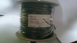
Inspired by you (Charlie, Jer, Syborg and others) I thought it would be interesting and beneficial for new builders if I documented my progress so here is a picture of the cable I ordered to make the wire stators:
Sourced from Farnell: MC7/0.2 TYPE 2 BLK 500M WIRE, 500M, 7/0.2MM, COPPER, BLACK
Inspired by you (Charlie, Jer, Syborg and others) I thought it would be interesting and beneficial for new builders if I documented my progress so here is a picture of the cable I ordered to make the wire stators:
An externally hosted image should be here but it was not working when we last tested it.
Sourced from Farnell: MC7/0.2 TYPE 2 BLK 500M WIRE, 500M, 7/0.2MM, COPPER, BLACK
Attachments
Last edited:
thanks for this update on the electrics Charlie
Jazzman's DIY Electrostatic Loudspeaker Page: The Electronics Package
Jazzman's DIY Electrostatic Loudspeaker Page: The Electronics Package
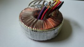
The toroidal transformers I ordered:
Attachments
The toroidal transformers I ordered:
That one will work but I think the single primary 50VA 230v/2x6v version linked on my website would be a better choice.
Last edited:
That one will work but I think the single primary 50VA 230v/2x6v version linked on my website would be a better choice.
This one:
Thanks Charlie, I'm going to see if I can get an exchange on the toroidals. On a slightly different issue I'm having trouble getting the licron crystal in the UK, does anybody have any suggestions? (I've reluctantly earmarked the elvamide!)
A couple of questions regarding the electronics, what does the transformer do on the bias run, Syborg mentioned it isolates the mains supply from the circuit, can somebody explain a bit more about the hows and the whys?
Also what does the connection from the bias supply through to the toroidals do? Or why is that there? Please forgive my ignorance.
A transformer magnetically couples the primary to the secondary. This means there is no direct electrical connection from the mains voltage to the bias circuit. In the US, where our power is 115VAC, the transformer also steps up the voltage from the 115V to 230VAC. The series of capacitor-diode voltage doublers then step up the 230V AC to 3KV DC. See my HV Supply page in the site in the signature line for a discussion on how this works.
The bias voltage has to be referenced to something, as a voltage is a just differential between two points. The 0V reference (common) of the bias supply is attached to the center tap of the transformer tree. Then the audio signal on the transformers (which goes to the stators) has a common reference point to the charge on the diaphragm.
The bias voltage has to be referenced to something, as a voltage is a just differential between two points. The 0V reference (common) of the bias supply is attached to the center tap of the transformer tree. Then the audio signal on the transformers (which goes to the stators) has a common reference point to the charge on the diaphragm.
- Status
- This old topic is closed. If you want to reopen this topic, contact a moderator using the "Report Post" button.
- Home
- Loudspeakers
- Planars & Exotics
- New build questions