Brian has an .xsl spreadsheet on his website, right where you bought the boards from. It lists the parts for the PSU board.
IIRC, it's got place for 4 TO-220diodes+ heatsinks, 3x2 caps of up to 40mm, 3x2 3W resistors per rail and a 2x MKP bypass caps. Check the spreadsheet for details.
thanks for the reply;
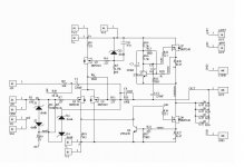
unfortunately, I presume to commit a mistake of looking on the website of Brian, in fact, is the voice of PCBs on the amplifier, that the voice of PCBs on the PSU, I get always the list of components relating to the construction of the section amplifier,,, I find no trace of the parts list for power supply;
give me additional help, I list the components on the PCB signed and you show me the right value:
C0 = ?
D0 = ? (diode zener)
R0 = ?
R1-2-3-4-5-6-7-8-9-10-11-12 = ? (power resistor)
D1-2-3-4 = ?
C1-2-3-4-5-6 = ? (rectification caps)
C7-8 = ? (bypass caps)
thanks
This is just a CRC power supply with a power indicator, parts choice is up to you.
C0 - anything that fits, it just smooths the power indicator LED, a few uf will do
D0 - general purpose diode like 1n4007.
R0 - your choice, set to limit current in LED to desired value based on LED choice and supply voltage. A few mA in the LED is usually enough. You can omit these parts if you don't want a power on indicator.
R1,2 - bleeder resistors - resistance and power rating to give your desired discharge time based on total capacitance and rail voltage. Can be omitted.
R3-12 - Whatever it takes to get to your desired resistance and power rating. Can be 0R if you want just a big C or can be a single off board high power R. A decent starting point is 0R33 or 0R47, 3W - caution if you use this for more than a mini you may need higher power ratings.
D1-4 - your favorite TO-220 dual lead rectifier. MUR2020 would work, there are other choices
C1-6 - your favorite brand of snap in cap, virtually any known terminal pattern, 40 mm diameter or less suitably rated in excess of your planned rail voltage. Use as much or little capacitance as you'd like.
C7-8 - not absolutely necessary, but your favorite radial cap with 5mm or 7.5mm lead spacing somewhere in the neighborhood of 1 uf.
Not a lot of help, but parts choice can be very personal. I use a lot of Apex Jr.Home Page surplus caps, others have their favorites that they wouldn't buy anything but new.
Of course I forgot to make the point that inspired me to post in the first place -
These amps will sound great with industrial grade components.
Sure there are tweaks and audiophile grade parts may that improve things a tiny bit, but you won't have regrets ordering parts from Digikey, Mouser and ApexJr. Other than parts that are supposed to be matched, most Pass designs can tolerate a range of absolute component values and still perform as intended.
Build and enjoy. Then consider tweaking. I doubt that you'll be motivated to open up the case.
Last edited:
Just a couple of questions, as I'm planning on building this amp this coming winter.
BrainGT's schematic indicates ZTX450, whilst I have a load of MPSA18 (as used in the Aleph30). Any benefit in using the ZTX450 over the MPSA18?
Also, if not using the -in input, most are shorting to gnd. Why not just leave out R9, R10 and C1, saving on components?
Thanks
BrainGT's schematic indicates ZTX450, whilst I have a load of MPSA18 (as used in the Aleph30). Any benefit in using the ZTX450 over the MPSA18?
Also, if not using the -in input, most are shorting to gnd. Why not just leave out R9, R10 and C1, saving on components?
Thanks
As Bill Fuss demonstrated in the Aleph J thread (IIRC), the ZTX450 starts turning on at higher voltage than the MPSA18. If you want to use your MPSA18s use around 1K for R17.
When single ended leave in R9, R10 and C1, otherwise you have 100% feedback. Ground the negative input when single ended.
When single ended leave in R9, R10 and C1, otherwise you have 100% feedback. Ground the negative input when single ended.
Boris, Power consumption depends on rail voltage and the bias you set. At 1A and 20V rails, it's about 40W (plus a little for the front end and PSU losses). Depending on the inrush current (how big is your transformer and filter bank) 0.5A or 1A should do for your line fuse.
IRFP240 maximum Junction temperature is 150C, but shoot for around 100C or less for reliability. Two devices on a heat sink will have an effective junction to sink thermal resistance of around .8 C/W. Add that to your sink's thermal resistance to air and multiply by ~40W and you have your junction temperature above ambient.
Sounds like you may have already built the amps. The poor man's check of suitable temperature is "can I put my hand on the heat sink for at least a few seconds?" If yes and you have a good thermal connection from the devices to the sink, you're probably OK.
are there any of the SMD version boards around? seems this thread has been around for ages and I love the design, would use for a high powered balanced headphone amp for 600R cans. I will continue to search the thread to see, but in the meantime if anyone could be bothered to answer such a lazy request it would be appreciated 
are there any of the SMD version boards around? seems this thread has been around for ages and I love the design, would use for a high powered balanced headphone amp for 600R cans. I will continue to search the thread to see, but in the meantime if anyone could be bothered to answer such a lazy request it would be appreciated
Some were made:
http://www.diyaudio.com/forums/pass-labs/52188-new-aleph-mini-pcb-gb.html#post582507
Don't know if they are available though.
As Bill Fuss demonstrated in the Aleph J thread (IIRC), the ZTX450 starts turning on at higher voltage than the MPSA18. If you want to use your MPSA18s use around 1K for R17.
When single ended leave in R9, R10 and C1, otherwise you have 100% feedback. Ground the negative input when single ended.
@ Woodenhead - I messed that one up - use <100R for R17 or 1K for R21 and 221 for R17. The reason for these parts is short circuit protection. you can leave them out completely if you are careful.
HI Bob,
Thanks for the fast reply. I just tried the new amp. Sounds really nice! Enough power for my speakers!
I have build the 20V version. A "1.4 A fast" fuse blew up. I have a stereo pair with one transformer of 500VA of 2x15V. I put in a "2.0 A slow" and it works. Hope that is ok.
The temperature rises to 60°C. I think I will put some ventilation inside the enclosing!
The offset is 30mV and 40mV. Is that ok? I don't know how to minimize that value!
Thanks a lot for the help!
I will post some pictures when its finished!
Some were made:
http://www.diyaudio.com/forums/pass-labs/52188-new-aleph-mini-pcb-gb.html#post582507
Don't know if they are available though.
yes, twas that pic and post that made me ask the question
 guess i'll ask Brian if he kept any. I would prefer SMD partially because I already have most parts in my parts bin, but also because its heaps quicker to build and should perform better too. anyway I guess i'll ask; thanks
As Bill Fuss demonstrated in the Aleph J thread (IIRC), the ZTX450 starts turning on at higher voltage than the MPSA18. If you want to use your MPSA18s use around 1K for R17.
When single ended leave in R9, R10 and C1, otherwise you have 100% feedback. Ground the negative input when single ended.
I went back and looked at the current limiter section in most of the Aleph schematics and the only one I found that could have a distortion problem is the Aleph J so everyones' projects should be trouble free. The Master has stated that the ZTX parts start causing distortion at .4Vbe so anyone building an Aleph J should raise R13 to at least 500 ohms, and 1K if they are using something other than the ZTX450 for Q3. I have heard from another forum member that ran into the same situation at higher output levels and was using the ZTX parts.
I still think it was a typo on the schematic.
The offset is 30mV and 40mV. Is that ok? I don't know how to minimize that value!
Those are good enough values, if you want lower values adjust R8 (see schematic). I used a trimmer.
Attachments
- Status
- This old topic is closed. If you want to reopen this topic, contact a moderator using the "Report Post" button.
- Home
- Amplifiers
- Pass Labs
- New Aleph Mini PCB GB