Banned
Joined 2002
Re: Isolation pads
Nice looking design there. ... I prefur the thick ceramic pad's..
Reason one.. If you get a piece os metal of any sort under it.. it wont dead short a fet..
Second they are great for heat transfer.
J'
Tarasque said:jleaman
I used special silicone pads. Rth~0,15C/W
Have a look at my project: http://www.passdiy.com/gallery/amini-p5.htm
Nice looking design there.
... I prefur the thick ceramic pad's..Reason one.. If you get a piece os metal of any sort under it.. it wont dead short a fet..
Second they are great for heat transfer.
J'
Banned
Joined 2002
I like those ceramic pads as well, I got few from Anthony (Coulomb) a while back and have used nothing else since. The extra height is perfect to make use of some really nice, extra tall, copper stand-offs that I bought at a military surplus shop. The pads are nice to the touch as well, now I toy with one constantly while I read or think.
Banned
Joined 2002
Illusus said:I like those ceramic pads as well, I got few from Anthony (Coulomb) a while back and have used nothing else since. The extra height is perfect to make use of some really nice, extra tall, copper stand-offs that I bought at a military surplus shop. The pads are nice to the touch as well, now I toy with one constantly while I read or think.
I got my first pair from Peter Daniel. And now i don't use any thing else...
J'
Aleph Mini/30
I am just now getting to my Aleph Mini's, do I understand correctly that C1 should be installed opposite to that indicated on the board?
For PSU boards do I have this correct?:
1-R3, R12 jumper is "standard" PSU
2-R3-R12 with appropriate R is CRC
3-R3, R12 with appropriate L is CLC
thanks,
SteveA
BrianGT said:
You are correct. Thank you for pointing out this error. I will put an update on the website. Here is a comparison of the schematic and the manual. I am sorry for the mistake. I will send out a mass e-mail about this soon.
The prototype amp (same amp board layout) has C1 with the polarity backwards and worked without problems:
http://www.briangt.com/gallery/miniALEPH-prototype/Brian_GT_Mini_Aleph_044_copy
I will talk to Mark and see if he noticed any problems. Sorry about this issue.
One more issue that I found last night, if you are using the 4 pin caps on the power supply board, you will want to remove the 2 unused pins, as the connected to the + capacitor lead, and this might cause problems. I will include this in a mass mail, and I will put an update on the webpage.
--
Brian
I am just now getting to my Aleph Mini's, do I understand correctly that C1 should be installed opposite to that indicated on the board?
For PSU boards do I have this correct?:
1-R3, R12 jumper is "standard" PSU
2-R3-R12 with appropriate R is CRC
3-R3, R12 with appropriate L is CLC
thanks,
SteveA
Re: Aleph Mini/30
Steve,
You are correct on all of these points.
--
Brian
SteveA said:
I am just now getting to my Aleph Mini's, do I understand correctly that C1 should be installed opposite to that indicated on the board?
For PSU boards do I have this correct?:
1-R3, R12 jumper is "standard" PSU
2-R3-R12 with appropriate R is CRC
3-R3, R12 with appropriate L is CLC
thanks,
SteveA
Steve,
You are correct on all of these points.
--
Brian
Sorry to drag out this old thread again....
Ok. I FINALLY got around to assembling 2 boards and have a couple of quick questions before I install them in a chassis.
The caps supplied in my stereo Mini-A / A30 kit were 6 electrolitics, a blue one (polyester?) and a small film one.
Of course the 3 electrolytics are easy as C1, C2 and C3 with C1 being the wrong orientation on the board silk screen.
But That only left me wth 2 caps of different values / types.
Was my kit short the matching parts or are some not required?
I have empty spots for C4 and C5 on both boards and only 2 caps. Which one goes in which spot, and I will order matching caps for the 4 boards I have.
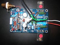
Also does anyoe have a close up picture of their boards completed so I can compare? I think Jason posted or sent one earlier but I've had to change PC's since then and have "lost" my references. Mother board died and I ended up purhasing a new PC versus trying to find an old RAMBUS mother board.
Any assistance would be appreciated.
Ok. I FINALLY got around to assembling 2 boards and have a couple of quick questions before I install them in a chassis.
The caps supplied in my stereo Mini-A / A30 kit were 6 electrolitics, a blue one (polyester?) and a small film one.
Of course the 3 electrolytics are easy as C1, C2 and C3 with C1 being the wrong orientation on the board silk screen.
But That only left me wth 2 caps of different values / types.
Was my kit short the matching parts or are some not required?
I have empty spots for C4 and C5 on both boards and only 2 caps. Which one goes in which spot, and I will order matching caps for the 4 boards I have.
Also does anyoe have a close up picture of their boards completed so I can compare? I think Jason posted or sent one earlier but I've had to change PC's since then and have "lost" my references. Mother board died and I ended up purhasing a new PC versus trying to find an old RAMBUS mother board.
Any assistance would be appreciated.
Banned
Joined 2002
hile reviewing this ENTIRE thread I noticed the following which I missed initially:
http://www.diyaudio.com/forums/showthread.php?postid=635468#post635468
Notice the position of the blue caps on Brians brds..
Now look at his picture and see where his blue caps are located:
http://www.diyaudio.com/forums/showthread.php?postid=655529#post655529
And Jason's...
http://jleaman.ath.cx/minia/IMG_2308.JPG
So where do the blue (poly?) caps go?
And my next question / concern:
I built my brds with the parts in the kit. The bag said A30 x 2 and the parts matched my BOM.
But noticing on the right in the notes field R12, R13 and R17 have notesabout "other" placements...
So what is the difference on the MAIN board between the Mini-A and the A30 other than remotely located transistors?
Banned
Joined 2002
rabstg said:hile reviewing this ENTIRE thread I noticed the following which I missed initially:
http://www.diyaudio.com/forums/showthread.php?postid=635468#post635468
Notice the position of the blue caps on Brians brds..
Now look at his picture and see where his blue caps are located:
http://www.diyaudio.com/forums/showthread.php?postid=655529#post655529
And Jason's...
http://jleaman.ath.cx/minia/IMG_2308.JPG
So where do the blue (poly?) caps go?
And my next question / concern:
I built my brds with the parts in the kit. The bag said A30 x 2 and the parts matched my BOM.
But noticing on the right in the notes field R12, R13 and R17 have notesabout "other" placements...
So what is the difference on the MAIN board between the Mini-A and the A30 other than remotely located transistors?
Make it look like this..
http://gallery.zorby-audio.com/displayimage.php?album=1&pos=7
This cant be to hard..if it is please pm me.
jleaman said:
Make it look like this..
http://gallery.zorby-audio.com/displayimage.php?album=1&pos=7
This cant be to hard..if it is please pm me.
Since not all the parts were included in your kits, and since I trust brian's Engineering, I am doing a bit more research.
As an example of my hesitation:
C6 47nF BC2068-ND BC Polypropylene 47nF capacitor for D5
A little further digging and I found tha my OLD excel ss I printed did not have the above note on the side of C6 which I am just finding.
C6 is http://www.rapidelectronics.co.uk/r...CAT_CODE=30153&STK_PROD_CODE=M27985&XPAGENO=1
which should be on top of the Zener.
Nothing personal, but I've never lost smoke from DIY electronics before.. Only a few fuses... And I don't intend to start now.
rabstg,
Do you have this parts list for A30 and mini-A from Brian's web site? It should provide some answers to your questions.
http://www.diyamps.com/aleph/docs/miniALEPH-parts_list.xls
I ordered the parts that were shown on Brian's part list and it work out fine. Every part fits perfectly.
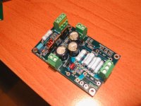
Here's a picture of my A30 stuffed board.
Do you have this parts list for A30 and mini-A from Brian's web site? It should provide some answers to your questions.
http://www.diyamps.com/aleph/docs/miniALEPH-parts_list.xls
I ordered the parts that were shown on Brian's part list and it work out fine. Every part fits perfectly.
Here's a picture of my A30 stuffed board.
Attachments
Banned
Joined 2002
- Status
- This old topic is closed. If you want to reopen this topic, contact a moderator using the "Report Post" button.
- Home
- Amplifiers
- Pass Labs
- New Aleph Mini PCB GB