jacco vermeulen said:
I usually cheat with manufacturer data books, but you can get a goodlooking one straight from => Sanyo
Thank you very much. A lot more information than the two page version I had.
jacco vermeulen said:
The Fairchild TN's have different max fT values and specified at 100mA, 250 and 150 MHz.
At 30mA, the fT numbers will be much lower, the lower voltage TN6727a PNP will be marginally better at 140MHz.
Sanyo's A1209/C2911 do 150/190MHz at that current level, can easily handle more than 30mA, pretty cool TO126 devices imo.
How about MJE171/MJE181? I have couple ten pairs ordered from Mouser ready to use.
john curl said:Peak Ft should be another consideration. For lower current drivers, h(re) can be interesting to consider. (Put that in your pipe and smoke it, Scott and Bob)
Unfortunately most datasheets do not tell much about the "h" parameters, except for hfe. But I will continue looking.
The 2SA1209/2SC2911 have their highest ft in the 20-50mA range (almost like a plateau) and hfe is linear and begins barely to drop at 50mA, this is why I think they might be usable here.
HKC said:
How about MJE171/MJE181? I have couple ten pairs ordered from Mouser ready to use.
These would need even higher currents (200 - 300mA), no ?
I see. I will omit the HP type additions (I will need the relatively small space for the heatsinks anyway).
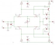
Attached is the schematic in it´s latest version (for now ;-) ), each Fet will run at 12mA, and the BJTs at about 50mA.
Next thing will be to change the capacitors to polypropylene types and to master Eagle PCB which is new to me (last time I used such a program it was running on DOS in the early 90ties ). I will report any progress here but it will take some time.
@HKC Did you already start with the phono stage ? Maybe we could discuss it here.
gk7 said:I see. I will omit the HP type additions (I will need the relatively small space for the heatsinks anyway).
Attached is the schematic in it´s latest version (for now ;-) ), each Fet will run at 12mA, and the BJTs at about 50mA.
Next thing will be to change the capacitors to polypropylene types and to master Eagle PCB which is new to me (last time I used such a program it was running on DOS in the early 90ties ). I will report any progress here but it will take some time.
@HKC Did you already start with the phono stage ? Maybe we could discuss it here.
Hi gk7
I am about to send the pcb document to factory for boards fabrication. I decided to use my own layout for the phono and RIAA sections. I will post photos once the boards are finished.
AndrewT said:GK,
your choice of 20r for R4 is almost correct.
You need some adjustment to balance the front end currents, otherwise this balance will vary with component parameters.
22r//500VR will give a nice range of adjustment.
Andrew, did you actually read the thread ? (Post #131, Post #138, Post #148 ...)
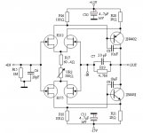
Have you ever looked at the original schematic ? (see attachment)
Attachments
gk7 said:Oops, forgot the attachment.
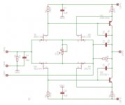
It's annoying to see you still don't show the inverting input as externally connectable.
syn08 said:
It's annoying to see you still don't show the inverting input as externally connectable.
Sorry that you get annoyed so easily ;-)
But your´re right it was missing.
I have assigned the pin numbers like in my Post #76
Attachments
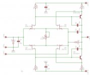
AndrewT said:I am commenting on your latest schematic and reminding you to design in some adjustment to allow for parameter variations.
The original does not use such an adjustment and later Designs with this type of circuit (Parasound) do not use it. It´s obviously superfluous.
HKC said:
Hi gk7
I am about to send the pcb document to factory for boards fabrication. I decided to use my own layout for the phono and RIAA sections. I will post photos once the boards are finished.
Did you design an entirely new schematic or are you referring to the pcb layout only ? In the latter case what did you substitute for the Fets ?
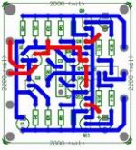
gk7 said:
Did you design an entirely new schematic or are you referring to the pcb layout only ? In the latter case what did you substitute for the Fets ?
I am referring to the pcb layout only. Please see attached phono stage layout. Schematic is based on original JC-2. As to the JFets I will use K170/J74. Size of board is 50 x 50mm
Attachments
- Home
- Source & Line
- Analog Line Level
- Need to build JC 2 preamp