I am going through the process of choosing a 10 inch pro woofer to mate with a B&C DE250 and RCF H100 horn in a ported enclosure. Crossover around 1.5khz.
This is my list so far:
B&C 10NW64 http://www.parts-express.com/pdf/294-679.pdf
Seems good though large peak at 2khz
B&C 10HPL64 http://www.parts-express.com/pdf/294-678.pdf
OK response to just over 2khz however I have heard the distortion figures for this driver are not great
B&C 10PLB76 http://www.parts-express.com/pdf/294-659.pdf
Qts is VERY low at 0.19. Not sure if this will be problem?
I would like to get the woofers from parts express simply because I have had the least amount of hassle with delivery to australia. So my choices are limited by their range.
Try here you may be able to get a good driver locally.
P-Audio Thailand
P.Audio System Co., LTD
This 12" Mid Base Driver should work well in a reflex enclosure.
http://www.paudiothailand.com/pdf/products/FL-12MB.pdf
Distributor Australia
Cannon Sound and Light Pty Ltd.
Mr. Daniel Trevor
Email: admin@cannonsound.com
Regards,
WHG
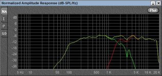
I have started playing with crossover simulation for the woofer & CD combo. This is mainly for fun / learning since I will measure the drivers when they arrive to try and crossover at the correct points to achieve smooth polar response.
Frequency graphs are copied using SPL trace, the CD + WG is from the driver vault (DE250 + OS waveguide) - should be more or less similar to the DDS waveguide.
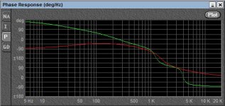
I have attached graphs of frequency and phase response for the 2 drivers using the following crossovers:
woofer: 1.8khz 4th order LR
CD: 1.8Khz 2nd order LR
I'll admit that I have a poor understanding of phase shift in crossovers. I have used asymmetric slopes because this seemed to give me the smoothest response. However Im hoping someone could explain what is happening in the phase graph so that I can start to understand what it all means.
Note that crossover will be active (DCX 2496)
Frequency graphs are copied using SPL trace, the CD + WG is from the driver vault (DE250 + OS waveguide) - should be more or less similar to the DDS waveguide.
I have attached graphs of frequency and phase response for the 2 drivers using the following crossovers:
woofer: 1.8khz 4th order LR
CD: 1.8Khz 2nd order LR
I'll admit that I have a poor understanding of phase shift in crossovers. I have used asymmetric slopes because this seemed to give me the smoothest response. However Im hoping someone could explain what is happening in the phase graph so that I can start to understand what it all means.
Note that crossover will be active (DCX 2496)
Attachments
Last edited:
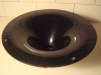
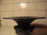
Drivers have arrived and the waveguides are better than I expected - quite rough on the back but very smooth and consistent where it counts. There are some bubbles and minor scratches on the external face but other than that I am happy.
Attachments
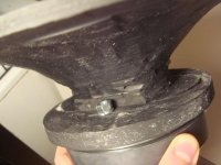
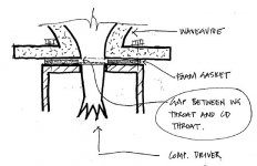
Only gripe is with the foam gasket on the comp driver - The hole is larger than the driver and WG throat. So when I connect them, there is an obvious gap. I drew up a sketch to illustrate the problem (please ignore the wacky scale). Perhaps I should remove the gasket to achieve a smoother transition?
Attachments
Do you know if it effects the response at all?
Also, do you know if the mouth angle of the CD matches the throat angle of the waveguide, I have always been curious about that.
I have read something about using felt cut into a ring helps with the transistion but I have not found real data and my tests showed very little difference.
Also, do you know if the mouth angle of the CD matches the throat angle of the waveguide, I have always been curious about that.
I have read something about using felt cut into a ring helps with the transistion but I have not found real data and my tests showed very little difference.
No-Air
Air leaks, particularly in the throat/neck of the horn, will kill its function. A gasket is required. Make/Buy a new one. Note, that when compressed, the gasket hole will become smaller.
Regards,
WHG
Only gripe is with the foam gasket on the comp driver - The hole is larger than the driver and WG throat. So when I connect them, there is an obvious gap. I drew up a sketch to illustrate the problem (please ignore the wacky scale). Perhaps I should remove the gasket to achieve a smoother transition?
Air leaks, particularly in the throat/neck of the horn, will kill its function. A gasket is required. Make/Buy a new one. Note, that when compressed, the gasket hole will become smaller.
Regards,
WHG
Matched Pair, Only
Slope of the horn wall at entry should match that at the driver exit. Use of a gasket to achieve an air-tight seal is mandatory. An air-leak will kill the horn function.
Any physical discontinuity in the inner wall of the horn will be seen by the outbound wave as an acoustical impedance discontinuity. This will cause generation of a back wave and may trigger transverse standing wave modes within the horn as well. The severity of these conditions will be dependent on signal wavelength (frequency) and the dimensions of the discontinuity, particularly when they are of comparable magnitude.
Regards,
WHG
Do you know if it effects the response at all?
Also, do you know if the mouth angle of the CD matches the throat angle of the waveguide, I have always been curious about that.
I have read something about using felt cut into a ring helps with the transistion but I have not found real data and my tests showed very little difference.
Slope of the horn wall at entry should match that at the driver exit. Use of a gasket to achieve an air-tight seal is mandatory. An air-leak will kill the horn function.
Any physical discontinuity in the inner wall of the horn will be seen by the outbound wave as an acoustical impedance discontinuity. This will cause generation of a back wave and may trigger transverse standing wave modes within the horn as well. The severity of these conditions will be dependent on signal wavelength (frequency) and the dimensions of the discontinuity, particularly when they are of comparable magnitude.
Regards,
WHG
Tacking with the Sound
Before getting into the finer points, what I see is a need to change design strategy. Frequencies below 80-100 Hz should be covered by sub-woofer(s).
For the mid-bass, use sealed enclosures that do not unload the drivers at low frequencies. An MTM configuration here would be preferred as well.
This tack will vastly improve system performance, especially when the cost of most the extra electronics has already been sustained.
Regards,
WHG
I have started playing with crossover simulation for the woofer & CD combo. This is mainly for fun / learning since I will measure the drivers when they arrive to try and crossover at the correct points to achieve smooth polar response.
Frequency graphs are copied using SPL trace, the CD + WG is from the driver vault (DE250 + OS waveguide) - should be more or less similar to the DDS waveguide.
I have attached graphs of frequency and phase response for the 2 drivers using the following crossovers:
woofer: 1.8khz 4th order LR
CD: 1.8Khz 2nd order LR
I'll admit that I have a poor understanding of phase shift in crossovers. I have used asymmetric slopes because this seemed to give me the smoothest response. However Im hoping someone could explain what is happening in the phase graph so that I can start to understand what it all means.
Note that crossover will be active (DCX 2496)
Before getting into the finer points, what I see is a need to change design strategy. Frequencies below 80-100 Hz should be covered by sub-woofer(s).
For the mid-bass, use sealed enclosures that do not unload the drivers at low frequencies. An MTM configuration here would be preferred as well.
This tack will vastly improve system performance, especially when the cost of most the extra electronics has already been sustained.
Regards,
WHG
The gap between the CD and WG throat is about 1mm. I will take some measurements once I have built the test cabinet. I can't see how a clean transition can be achieved without removing the mesh screen on the CD though - not too keen on doing that but maybe I will have to.
It is difficult to tell if the mouth slopes match, I will need to shine a torch down there to check.
With respect to changing to a sealed enclosure, I feel I may be satisfied with bass reflex considering the size of the room and previous experience with similar BR pro woofer systems. Im aware of the compromises and always have the option of 'blocking' the vents and adding a sub/s. I will most likely do this in the future when we move into a larger space.
The gap between the CD and WG throat is about 1mm. I will take some measurements once I have built the test cabinet. I can't see how a clean transition can be achieved without removing the mesh screen on the CD though - not too keen on doing that but maybe I will have to.
It is difficult to tell if the mouth slopes match, I will need to shine a torch down there to check.
With respect to changing to a sealed enclosure, I feel I may be satisfied with bass reflex considering the size of the room and previous experience with similar BR pro woofer systems. Im aware of the compromises and always have the option of 'blocking' the vents and adding a sub/s. I will most likely do this in the future when we move into a larger space.
Do not mess with the bug screen. Just make sure you have a air tight seal between the horn and driver.
Regards,
WHG
off-axis measurements
I have some empty open baffles sitting around and will mount the waveguides for a few quick measurements over the weekend.
Silly question about off-axis measurements - is the centre point of rotation around the driver centre or the WG mouth/baffle centre?
I have some empty open baffles sitting around and will mount the waveguides for a few quick measurements over the weekend.
Silly question about off-axis measurements - is the centre point of rotation around the driver centre or the WG mouth/baffle centre?
10HPL64 + DE 12-8 + W. Horn.
An externally hosted image should be here but it was not working when we last tested it.
An externally hosted image should be here but it was not working when we last tested it.
Regards zeoN_Rider
A wooden horn lens!
Brilliant, I just found my next project!
- Status
- This old topic is closed. If you want to reopen this topic, contact a moderator using the "Report Post" button.
- Home
- Loudspeakers
- Multi-Way
- Need opinions for 10" pro woofer + horn build