If you still have the chokes you used in the prototypes I would substitute those for the ones in the finished project temporarily. I think the results could be very interesting.. It would at least answer the question as to whether or not the chokes you got new are the culprit or not. (I wouldn't be too surprised)
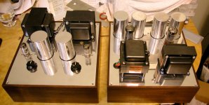
The choke in the old stereo supply wasn't that good and not built to the level of Bud's. I'm sure the old stereo circuit somehow filtered more but maybe something else is affecting it. The ripple is nearly to the volt on each side. Bud's iron is really overbuilt and wonderfully shielded. Here's a pic of the pre.
Attachments
Hi there,
if chassis space ist not a problem:
One could probably find a transformer with two separate, sufficiently isolated 20-30V windings and connect one of them in series with each 200V winding of your power transformer. Mind correct phases/polarities.
If you really want a choke-input supply, there is no other way to raise the output voltage than to give it a higher AC input.
Greetings,
Andreas
My thoughts as well....or a couple of 'bell' transformers...
Hi Andreas,
Why would you need exactly 410V? What would be wrong with 400 or 420? Tube circuits are usually very tolerant against voltage changes.
What I always do on my custom power transformers is to have them with primary taps for +/- 5% adjustments.
Best regards
Thomas
by the way, this discussion is making me a bit nervous - having ordered my custom-wound power transformer last week, after extensively playing PSUD. Hope to get 410V from a 480V winding with a choke-input supply...
Why would you need exactly 410V? What would be wrong with 400 or 420? Tube circuits are usually very tolerant against voltage changes.
What I always do on my custom power transformers is to have them with primary taps for +/- 5% adjustments.
Best regards
Thomas
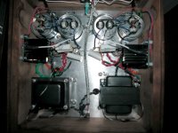
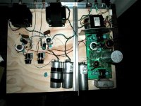
Judging by your photo of the underside of the PSU, I'd wonder whether you are suffering from 'ground bounce' due to your physical layout.I found enough caps to parallel. Voltages are set. Now I have to deal with ripple. I don't know if it was an effect but now with the C1 in there @ .32uF I'm getting .3vac ripple whereas before on the board with the choke loaded regulated supply I had .045vac
Any tips on exploring possible causes is greatly appreciated.
Basically in a PSU you don't want star grounding throughout, which appear to be what you have built. The problem is that unless you get the 'star' electrically *perfect*, you may accidentally include some of the ground currents from the first capacitor in your output voltage.
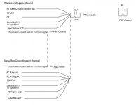
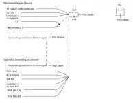
What you want is two 'common grounds'. The first one is at the bottom of C1. From here goes a connection directly to the transformer center tap, a connection to the bottom of C1, and a short wire to the second ground 'star'.
The second 'star' connects to the first as just described, to the bottom of C2/C3, the 100uF in total filter caps, and the output connector to the amp itself. The 100 ohm resistor in your photo looks to be a ground loop breaker, which presumably goes to the chassis. If this is so, then it need to be connected to the second star, at the bottom of C2/C3.
The wire between the two stars can be quite short, an inch or two is plenty, and the two physical stars can be quite close together if needed. You could for instance build a new, second star on the terminal of one of the filter caps.
The point of this exercise is to make 100% certain that none of the current through C1 is running through the output ground connection. Right now it looks like this is what you are doing.
With a 0.32uF cap for C1, my simulation gives 0.035Vrms of ripple on the output, so something is off now. I tried 'ruining' the rectifier tube by offsetting the individual diode resistances, but that hardly did anything. The 35mV is with a 'bad' rectifier BTW.
Either this, or Kevin's suggestion of trying the old chokes might be a good idea, just as a test.
- Frank.
There is another potential problem with your physical layout. You have the two wires going to the chokes twisted tightly together. There is a large electric AC field across those two wires, and even a small amount of capacitive coupling between them is enough to couple hum to the output. It probably doesn't help either that the wires are passing close to the heating and HT secondary wires.
You need to think of the choke as an isolator, with everything relating to the rectifiers and C1 on one side, and the output caps and the load at the other. Use longer connecting wires if needed, and minimize stray capacitance between the two sides. 10-20pF in the wrong place is enough to ruin your day.
Additionally it looks like the chokes are directly below the mains transformers, even though you have attempted to locate them so as to minimize the coupling of the stray magnetic fields. One simple test might be to temporarily pull one choke out of the chassis on long connecting wires and see if that changes anything.
Thanks everyone. That's all great information and I will experiment with suggestions. Frank the HT wires are are the opposite side of the tube but the choke wires do pass by the filament for the signal tubes and rectifier. I could extend it and have it loop up and over. I could also sleeve them in mess wire and ground it like I did for the mains AC that comes up to the front switch. I need to take a new picture today of the finish to better illustrate what's happening. I'll take a photo right now and turn it off. Its a shame to have what is looking like a great sounding pre be hobbled by this hum.
The choke in the old stereo supply wasn't that good and not built to the level of Bud's. I'm sure the old stereo circuit somehow filtered more but maybe something else is affecting it. The ripple is nearly to the volt on each side. Bud's iron is really overbuilt and wonderfully shielded. Here's a pic of the pre.
I understand what you are saying, but unless you have all of the gear and knowledge to test those chokes you won't have any idea whether or not as nicely as they are built they actually meet the electrical requirements for your application, and truthfully they look way too big to me for the amount of current they are meant to supply. Bigger is not always better... (Not my area of expertise, so take the size comment with a grain of salt, still I wouldn't take anything on faith since it clearly isn't working properly.)
Please give it a try..
The other suggestions particularly wrt to C1 and your star grounding are very good ones.. Need to make those changes too.
Last edited:
Definitely will explore those grounding changes. I appreciate your help. These chokes are 30H with a 200 Ohm DCR so they're about the right size for that. The other choke actually wandered its DCR so I sent it back to the local company. It wasn't anything to write home about. I've been dealing with Onetics for years and in my opinion Bud makes some of the best iron I've ever heard. It makes sense what you're saying if the psu circuit was identical. That choke was hidden behind a reg. circuit.
Last edited:
Original circuit on wood
I found a shot of it on the test board as reference. As you can see it was a different PSU and the iron was far apart from each other. Very close quarters now. I had the exact same grounding as shown in my drawing. I suspect I have something radiating in this build.
I found a shot of it on the test board as reference. As you can see it was a different PSU and the iron was far apart from each other. Very close quarters now. I had the exact same grounding as shown in my drawing. I suspect I have something radiating in this build.
Attachments
While Kevin is typing his explanation, I might jump in with another suggestion. ") I'd completely remove the 0.22uF in parallel with the 100 ohm, the ground loop breaker. Instead I'd use a pair of back-to-back diodes in that spot. Something cheap and hefty, like 3-5A: 1n5408 etc.
I'd completely remove the 0.22uF in parallel with the 100 ohm, the ground loop breaker. Instead I'd use a pair of back-to-back diodes in that spot. Something cheap and hefty, like 3-5A: 1n5408 etc.
The ground loop breaker's job is to *not* conduct anything during normal operation, least of all AC signals. You don't want a cap there. Instead the pair of diodes has a voltage jump of 0.7V in both directions, which needs to be exceeded before any noise can pass through. The job of the ground loop breaker is to only conduct when an error occurs, like a problem that might blow a fuse or similar.
- Frank.
I'd completely remove the 0.22uF in parallel with the 100 ohm, the ground loop breaker. Instead I'd use a pair of back-to-back diodes in that spot. Something cheap and hefty, like 3-5A: 1n5408 etc.The ground loop breaker's job is to *not* conduct anything during normal operation, least of all AC signals. You don't want a cap there. Instead the pair of diodes has a voltage jump of 0.7V in both directions, which needs to be exceeded before any noise can pass through. The job of the ground loop breaker is to only conduct when an error occurs, like a problem that might blow a fuse or similar.
- Frank.
When you said 'back to back' you mean each diode going in opposite directions? I have not experimented with that. I have tried the method I'm using and just a resistor without the cap and this one always provided better results. I can try this when I try your new grounding scheme provided I understand the orientation.
Last edited:
Yes, exactly. If your grounding is done properly, then you shouldn't be able to hear the ground loop breaker, unless it isn't there at all.When you said 'back to back' you mean each diode going in opposite directions?
Another detail I'd suggest if you don't have it already. Electrically connect your two chassis frames with a separate, sturdy grounding wire. (I use thumb screws for these connections). This is in addition to the ground and chassis connections in any connectors you use. You should consider doing this every time you have PSU and amplifier on separate chassis'.
The idea here is to always be 100.0% certain that the pair of chassis' are at the same potential. If you don't have this safety chassis connection, you might risk getting the full B+ voltage between the two chassis' if you are unlucky and breaks the ground connections in your multi-connectors. This might electrocute you, if you accidentally touches both boxes at the same time with two hands.
- Frank.
Edit: Also I'd add a ground loop breaker, two diodes, between signal ground and chassis in the amp.
OK, I'll try it. Yes both chassis are connected as you can see from the schematic. The top plate and back plate are connected to each other and a wire comes back through the umbilical from the signal chassis and meets up with the PSU chassis.
I'm not getting any ground loop noise. Just coupling noise and excessive ripple as mentioned. Could I also ask your opinion on another issue I didn't want to stray this topic with? Here's the link to the thread http://www.diyaudio.com/forums/tubes-valves/184038-b-ramping-up-before-ccs-filament-danger.html#post2486291
I'm not getting any ground loop noise. Just coupling noise and excessive ripple as mentioned. Could I also ask your opinion on another issue I didn't want to stray this topic with? Here's the link to the thread http://www.diyaudio.com/forums/tubes-valves/184038-b-ramping-up-before-ccs-filament-danger.html#post2486291
Kevin could you explain how Frank's method is shunting to ground better so there's no bounce? I'm having a hard time thinking on it. Yes, I agree, there is more probably going on. The 60 cycle sounds like transformer coupling.
Actually my concern relates the charging currents in C1. Frank's connection as shown provides a tight loop for the high charging currents in C1 and prevents wiring induced IR drops from modulating your grounds with ripple voltage induced by the charging current in that first cap. It may or may not make a subtle difference depending on the application, but the higher the charging currents the more important it becomes to segregate these charging currents from the rest of the ground circuitry.
- Status
- This old topic is closed. If you want to reopen this topic, contact a moderator using the "Report Post" button.
- Home
- Amplifiers
- Tubes / Valves
- Need Help. PSU not voltage down from design