What my thick head is still having problems with is its not separated since its also going to the second star ground. So the wire between the ground would have to act as some resistance since the speed of any electricity there wouldn't really be slowed. If you said put a diode between those two stars I would get it.
What am I missing? Is there a millisecond delay that achieves the desired result?
What am I missing? Is there a millisecond delay that achieves the desired result?
What my thick head is still having problems with is its not separated since its also going to the second star ground. So the wire between the ground would have to act as some resistance since the speed of any electricity there wouldn't really be slowed. If you said put a diode between those two stars I would get it.
What am I missing? Is there a millisecond delay that achieves the desired result?
You need to think in terms of current loops. All you are really trying to do is keep the capacitor charging current out of the rest of your ground wiring. You're simply confining the charging current to the transformer wiring and the terminal on the capacitor. (Try to think of where that current is coming from and where it is going. You don't want those charging currents flowing in any part of the load circuitry. The capacitor, not the rectifier should be providing the load current as a loop independent from the charging loop except at the point where they connect to the capacitor.) Has nothing to do with the speed of electrons flowing through the wires or delay or anything else, just a simple current loop.
.... and hum level identical. A friend told me a way to make a poor mans probe to use with a DMM. I'll give it a try. It may be transformer coupling. I had figured it out prior to drilling holes but that was without the circuit up and running.
Would that also account for the excessive ripple? BTW, the filament supply with the pseudo center tap to ground is .004vac same as on the bread board. So its not be affected in the close quarters.
Would that also account for the excessive ripple? BTW, the filament supply with the pseudo center tap to ground is .004vac same as on the bread board. So its not be affected in the close quarters.
.... and hum level identical. A friend told me a way to make a poor mans probe to use with a DMM. I'll give it a try. It may be transformer coupling. I had figured it out prior to drilling holes but that was without the circuit up and running.
Would that also account for the excessive ripple? BTW, the filament supply with the pseudo center tap to ground is .004vac same as on the bread board. So its not be affected in the close quarters.
A scope would be very helpful about now, you're kind of running blind at the moment. There are several possibilities, one is magnetic coupling from the chokes into your audio circuitry, another is electro-static (capacitive) coupling into the audio circuitry. You can do all sorts of interesting things to see whether or not the noise is coupling into various parts of your circuit.
Given the high ripple numbers you quote on the supply it is likely either the amplifier stages are not drawing the proper load current or the chokes are different than you expect. Try grounding the grids and seeing whether or not that makes any difference - if input referred noise it should go away, if supply related this will have no effect at all.
Ripply dc filament supplies can be much worse than pure ac due to the dv/dt of the ripple component and its ability to couple through cathode to filament capacitance as well as radiate into surrounding wiring.
So many thoughts, so little time, I'm off to the gym now..

More great input. Since the hum never gets any louder by opening the pots I don't think its in the circuit. I had those issues before and know what it sounds like. This is a steady 60 cycles not matter pot closed or wide open. So I don't think its input. As quoted above my DC filament is very low and same as before.
The amplifier stage is acting as before with voltage/current. I'll try the homemade probe but yes, I sure wish I knew someone in the L.A. area with a scope and a gift of an hour of exploration.
The amplifier stage is acting as before with voltage/current. I'll try the homemade probe but yes, I sure wish I knew someone in the L.A. area with a scope and a gift of an hour of exploration.
wiring shots 1
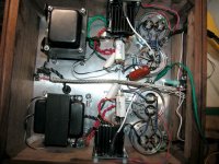
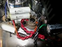
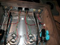
So far -- I unscrewed one channel choke and trans. My homemade ac probe didn't work. I new started playing orientation in every which way. Zero. I even had enough length to get the one choke out of the box. Zero. Turning the trans in one side made the ripple increase slightly. Nothing I did with the choke had any effect on the hum or ripple.
Tomorrow I will undo the output transformers and rotate them but I have a feeling something else is going on. Changing the orientations should have had some effect on the hum but it did not.
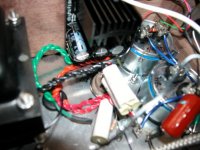
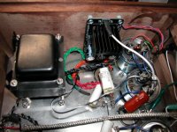
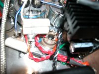
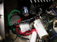
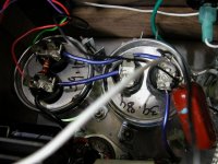
Here's a bunch of photos in case one of you can spot something obvious.
So far -- I unscrewed one channel choke and trans. My homemade ac probe didn't work. I new started playing orientation in every which way. Zero. I even had enough length to get the one choke out of the box. Zero. Turning the trans in one side made the ripple increase slightly. Nothing I did with the choke had any effect on the hum or ripple.
Tomorrow I will undo the output transformers and rotate them but I have a feeling something else is going on. Changing the orientations should have had some effect on the hum but it did not.
Here's a bunch of photos in case one of you can spot something obvious.
Attachments
So far -- I unscrewed one channel choke and trans. My homemade ac probe didn't work. I new started playing orientation in every which way. Zero. I even had enough length to get the one choke out of the box. Zero. Turning the trans in one side made the ripple increase slightly. Nothing I did with the choke had any effect on the hum or ripple.
Tomorrow I will undo the output transformers and rotate them but I have a feeling something else is going on. Changing the orientations should have had some effect on the hum but it did not.
Here's a bunch of photos in case one of you can spot something obvious.
All good things to try, might want to lengthen wires and move the output transformers further away from everything and see what effect that has on the noise. I expect this could be quite significant. I build a lot of transformer coupled things, and the power supplies are generally located on separate chassis or I get some noise.
If no significant improvement you might still want to try the chokes you used in the prototype.
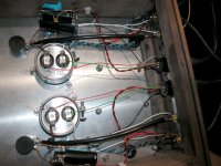
As you can see its two chassis. OTs are in the signal box. If you look at the picture of the prototype the choke is very far away from the trans but right beside the PCB. Again that choke is gone. If these were coupling shouldn't I have heard something once I changed all the orientation? I certainly have in the past. Moving a transformer around to find a null point was within 1/4 inch at times. These trans are build as isolation transformers and heavily shielded.
Since I could move the choke ALL around the internal chassis and no change in hum I'm kind of discounting them for the time being. One of the odd audio mysteries...
Since I could move the choke ALL around the internal chassis and no change in hum I'm kind of discounting them for the time being. One of the odd audio mysteries...
I took the time to do as much measuring as I could. I found a couple things. One rectifier socket was carrying 1vac because it didn't have connection with chassis (I have the on isolation dampening pads. Whereas the other has some connection with ground and it doesn't show AC. Ground it resolved the AC but didn't affect the hum.
The other thing I found was the CCS filament heat sinks had 1.35/1.8 vac on them. I'm a little concerned to just ground them as I don't know if that would harm the regulator.
These are ones I bought. DIYHFS Ultra Low Noise Filament Supply (Rev B2) 2-12V - eBay (item 230541340155 end time Mar-20-11 21:36:32 PDT) Although I didn't pay what they're asking now.
Would it be ok to ground those?
- Status
- This old topic is closed. If you want to reopen this topic, contact a moderator using the "Report Post" button.
- Home
- Amplifiers
- Tubes / Valves
- Need Help. PSU not voltage down from design