Fixed the previous one.Now I got this one.
Problem : I made the rem_bridge, it receieves 12v, the LED lights up, i can hear the rellay clicking on/off (ofc when i power it up, and when I turn it off).
Problem no sound in speakers.
The following : i have checked the tranzistors as in the previous pioneer model (gm-2000a ) and they all are in good order.Nothing is "fryed".
The thing is that I have 2 switchies in the amp somebody can tell me about them?
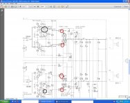
theyre highlited with black , and the reds are the final tranzistors.
Plese help.
Thx a lot !
p.s. 1
thers a single volume know in the form of a hole in the amp case, wich leds to a screw, turning it from 400mv to 4V, rca level input. if it helps
p.s. 2
i`ll attach documentary needed
Problem : I made the rem_bridge, it receieves 12v, the LED lights up, i can hear the rellay clicking on/off (ofc when i power it up, and when I turn it off).
Problem no sound in speakers.
The following : i have checked the tranzistors as in the previous pioneer model (gm-2000a ) and they all are in good order.Nothing is "fryed".
The thing is that I have 2 switchies in the amp somebody can tell me about them?
theyre highlited with black , and the reds are the final tranzistors.
Plese help.
Thx a lot !
p.s. 1
thers a single volume know in the form of a hole in the amp case, wich leds to a screw, turning it from 400mv to 4V, rca level input. if it helps
p.s. 2
i`ll attach documentary needed
Attachments
sorry...
this is the link for the schematics.
http://www.eserviceinfo.com/downloadsm/50455/Pioneer_GM1200, GM2200.html
this is the link for the schematics.
http://www.eserviceinfo.com/downloadsm/50455/Pioneer_GM1200, GM2200.html
Last edited:
The components circled in black are the bias potentiometers. They are used to set the idle current for the output transistors.
I see.I remember now. I read soemthing about the idle current for the other amp.Gm-2000a.
Question.In wich direction do I need to turn them?I can`t find anything on the itnernet about them.
If I go back and read about them on the gm-2000a amplifier, should I find similarities?
Thanks.
Generally, turning the bias post clockwise will increase the idle current. Turn them slowly to prevent excessive current flow through the output transistors. Have all transistors tightly clamped to the heatsink before attempting to adjust the bias.
the gm-2000a amplifier has them turned at half. both knobs.
for my information, whats the difference if I have them opned all the way , half, of if I turn them counterclockwise all the way??
in the manual of the gm-2000a it says for adjusment of the idle turn counter clockwise.turn power on and wait for 30 min.
whats that suppossed to mean?
If you turn them fully clockwise, the output transistors will likely overheat and fail.
You adjust them and let the amp idle (no speakers connected, no input signal) and re-check it. You have to do this to make sure that the bias doesn't drift and remains very near where it was set.
You adjust them and let the amp idle (no speakers connected, no input signal) and re-check it. You have to do this to make sure that the bias doesn't drift and remains very near where it was set.
If you turn them fully clockwise, the output transistors will likely overheat and fail.
You adjust them and let the amp idle (no speakers connected, no input signal) and re-check it. You have to do this to make sure that the bias doesn't drift and remains very near where it was set.
Thats a bit of a problem.I don`t remember wher it was set.foolish of me, I tempered with them.
Does your 12v power supply have an amp meter on it?
the test i`m doing are on the car battery.only way to find out the amps is to go with the multimeter and test in live.
connect the multimeter at the + - on the amp ?
If you don't have an amp meter on a 12v supply, measure the DC voltage from the emitter of one output to the emitter of the other transistor in one channel. Set the DC voltage (with the bias pot) to about 0.002v DC. I'd suggest installing a 10 amp fuse in the amp while adjusting the bias to provide additional protection in case you set the bias too high.
If you don't have an amp meter on a 12v supply, measure the DC voltage from the emitter of one output to the emitter of the other transistor in one channel. Set the DC voltage (with the bias pot) to about 0.002v DC. I'd suggest installing a 10 amp fuse in the amp while adjusting the bias to provide additional protection in case you set the bias too high.
i`m sorry but i don`t get it 100%.
i assume that you are saying to measure the amps of the tranzistors of one channel.
what is the "pot" ?
and where should I instal a dc fuse in the amp?change the 30 amp fuse with one of 10 amp(i doubt you would recommend this). if this is not the case then where should I install it?
The amp is supposed to have a 15 for normal operation. A 30 offers absolutely no protection. Install a 10 in the fuse holder on the amp while adjusting the bias.
You measure the voltage between the emitters of the output transistors for each channel.
If the amp is playing and not overheating at idle, it's likely good enough as it is.
You measure the voltage between the emitters of the output transistors for each channel.
If the amp is playing and not overheating at idle, it's likely good enough as it is.
The amp is supposed to have a 15 for normal operation. A 30 offers absolutely no protection. Install a 10 in the fuse holder on the amp while adjusting the bias.
You measure the voltage between the emitters of the output transistors for each channel.
If the amp is playing and not overheating at idle, it's likely good enough as it is.
ok.n00b question.get ready for it.
looking at the tranzistor fromt he front (writing part towards me)
| | |
B E C ?
I put the red probe (multimeter probe) and the black where?
I have checked the tranzistor in diode mode. but to be honest i checked each combination for results.did not know wich was wich at the tranzistors pins.
I think I saw it up somewhere on the internet when I did it.
There is only one emitter per transistor. There are only two output transistors per channel. Place one probe on one emitter and the other probe on the other emitter.
Correct me if I`m wrong.
one probe on the emiter pin on one of the tranzistors.
the other probe on the other emiter of the second tranzistor.
p.s.
if I re-charge a car bettery can I use it for testin?the car might be used tommorow by fammily members.
Thx for your time and patience.
p.s.2
change the 30 amp fuse of the amplifier with one of 10 amps correct? question : could it not fry instanly?beeing 1/3 of the amps? the amp says 30 amp fuse. If I replace it with a 10 amp fuse shouldn`t it burn instanly?.....or beeing in "test mode" with no input signal, no speakers attached, the amps needed would be much less used and therfore would be no problem/
Last edited:
You can use a battery for testing.
The amp only draws about 1 amp at idle.
The schematic diagram calls for a 15 amp fuse. Maybe the 30 amp is for the 2200 and the 15A is for the 1200.
ok.got it.
i`ll test it out tommorrow.
keep you posted.Anyhow I wi`ll have questions to ask again.
Thx a lot for your time and answers !
- Status
- This old topic is closed. If you want to reopen this topic, contact a moderator using the "Report Post" button.
- Home
- General Interest
- Car Audio
- Need help ! Pioneer GM-2200