I agree with Earl. I think that your nearfield measurement is suspect. That's not the only way to create low frequency data for the blender. I suggest that you instead measure the Thiele-Small parameters for the driver and use a box modeler to create the response. If you use Woofer Box and Circuit Designer you can export theTS model response as an FRD file. You then import that into the Blender as the low frequency data set and add the diffraction model to that, just like you would do with nearfield data.
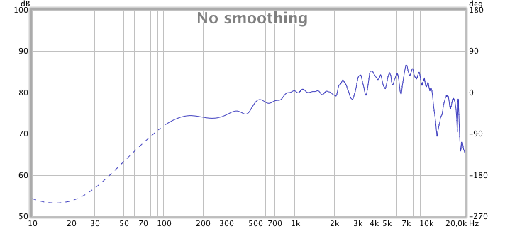
Does the driver have a whizzer cone? I am curious what might be causing the nearfield to have that dip at 300Hz. Any ideas?
Or use the built in box model in the blender. It's not as sophisticated as the full box model I used in the Woofer Box and Circuit Designer, but within reason the results match exceptionally well. Credit there goes to Don Keele who gave me the math I used for the simple box model that put in the Blender.
^
I'll redo the near field measurement on the "naked" driver without the box tomorrow.
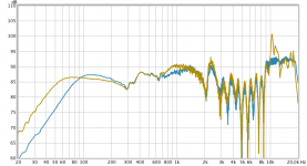
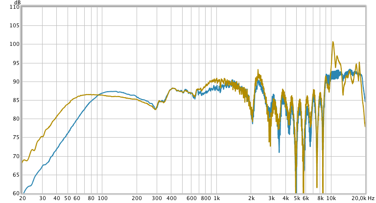
Here's near field (dust cap) of the driver in the box (blue) vs. free air (brown):
Attachments
Glad to see that people are finally starting to realize that an axial response alone is not enough to do a good crossover. Too much goes on off-axis that is important. I have been doing this for almost a decade now.
I use a finer set of data near the axis than further away since this is where one wants the better accuracy. I use 5 degrees up to 20, 10 degrees up to 60 and 20 degrees to 120, then 150 and 180. The data is then fit to a radiation model which yields 2 degree accuracy over the entire field. I only do horizontal polars currently as this is what matters most. There is always a pair of nulls above and below the horizontal plane and you have to look at these on occasion, but then one finds that they stay pretty well constant with the crossover point and separation distance and can be ignored for any other issues.
I think most did Earl, we were doing so with LMS/Leap close to 20yrs ago ..
I think we had already established the fact that power response has an audible effect. "It all depends" is not really a satisfying answer.
What's not appealing about it?
The deafening silence alone kills you ...
")
Thanks Charlie.
Regarding your 2nd question: the mic was a couple of mm from the dust cap.
Here's a ground plane measurement gated at 8,7ms:
Why are you gating a groundplane measurement .... ?
Here's near field (dust cap) of the driver in the box (blue) vs. free air (brown):
Is this at 2.83v ..?
Why are you gating a groundplane measurement .... ?
Because it was done in a room with the nearest boundary about 1.5m away.
Is this at 2.83v ..?
Does it matter?
Hi Jeff B,
In the book “Testing Loudspeakers” by Joseph D’Appolito, he says the following;
“The ground plane technique simulates two sources in free space positioned in mirror image along the measurement axis. For this reason, the effective baffle area is twice as large and the shape is different from that of the single system. There is also some mutual coupling between the DUT and its image. As a result, frequency response will be somewhat different from the free-space measurement.”
In light of this, would you recommend not using the ground plane technique for use with your baffle step simulation/blending program.
Regards
Peter
Groundplane Measurement is best for measuring outdoors at least 5m from the nearest building or reflective wall. Doing gating indoors is ******* in the Wind, just drag the cabinet outside ...
Yes, for best consistency and relavance almost best to use some kind of reference voltage ..
Because it was done in a room with the nearest boundary about 1.5m away.
Does it matter?
Yes, for best consistency and relavance almost best to use some kind of reference voltage ..
Hi Jeff B,
In the book “Testing Loudspeakers” by Joseph D’Appolito, he says the following;
“The ground plane technique simulates two sources in free space positioned in mirror image along the measurement axis. For this reason, the effective baffle area is twice as large and the shape is different from that of the single system. There is also some mutual coupling between the DUT and its image. As a result, frequency response will be somewhat different from the free-space measurement.”
In light of this, would you recommend not using the ground plane technique for use with your baffle step simulation/blending program.
Regards
Peter
Hi Peter,
I do cover that topic in the paper. Here is what I said:
Ground Plane Measurements –
Ground plane measurements can be effective, but do create some concerns. To perform ground plane measurements we place the mic and the speaker on a flat, smooth, highly reflective surface, with the microphone lying on the ground. The speaker will sit on the ground at least the minimum far-field distance from the mic (to be defined below). You may need to tilt the speaker downward toward the mic in order to maintain the proper axis during the measurement. The reflection from the ground creates a virtual mirror image of the speaker, so ground plane measurements are always 6 dB higher than half-space measurements due to this reflection.
One of the problems with ground plane measurements though are due to the fact that the virtual baffle is now twice as large as it really is and this will change the low frequency response some. Another problem is if the surface is not perfectly flat and very highly reflective, these will alter the response too. The advantage to the ground plane response is that if performed outdoors can provide response that is accurate to 20Hz or below. There is also the problem of ambient noise when measuring outdoors. In my neighborhood it just does not seem to lend itself to taking good measurements, and no one wants to take measurements in bad weather. There are techniques that can be used to get around some of the issues with ground plan measurements but they require some very precise distances and placement of the microphone and speaker to be accurate that other methods don’t require. For this reason I tend to stick with near-field and far-field measurements indoors and merge the data.
Std voltage is not important here, I think. But for actual speaker xo work it sure is. We must remember that it is winter now at northern hemisphere, outdoor measurements are out of question now, for this discussion. But again, for "a real case" necessary.
Sweat my **** off today, dirty greasy grimy and quite content after fixin up a friends elderly mothers car. Spent the afternoon chatting with Pops who's gotta be 80 now. Funny old greek guy from Kalamata, kinda raunchy, but ehhh it's all good. They want to adopt me, how sweet
Oh yeah, perhaps do ground plane measurements in the morning, wind permitting, aviation forecast looks good, with a chance of sea fog. tis 8pm and 21c out atm, wind 4kmh, patio door and windows open or it would be >26c inside... trying to keep from turning the ac on. Overnight low is 19c
Noise is not an issue if using a LMS type system. You can also place the cabinet top down and tilted over towards mic for less baffle effect ...
Hi Peter,
I do cover that topic in the paper. Here is what I said:
Ground Plane Measurements –
Ground plane measurements can be effective, but do create some concerns. To perform ground plane measurements we place the mic and the speaker on a flat, smooth, highly reflective surface, with the microphone lying on the ground. The speaker will sit on the ground at least the minimum far-field distance from the mic (to be defined below). You may need to tilt the speaker downward toward the mic in order to maintain the proper axis during the measurement. The reflection from the ground creates a virtual mirror image of the speaker, so ground plane measurements are always 6 dB higher than half-space measurements due to this reflection.
One of the problems with ground plane measurements though are due to the fact that the virtual baffle is now twice as large as it really is and this will change the low frequency response some. Another problem is if the surface is not perfectly flat and very highly reflective, these will alter the response too. The advantage to the ground plane response is that if performed outdoors can provide response that is accurate to 20Hz or below. There is also the problem of ambient noise when measuring outdoors. In my neighborhood it just does not seem to lend itself to taking good measurements, and no one wants to take measurements in bad weather. There are techniques that can be used to get around some of the issues with ground plan measurements but they require some very precise distances and placement of the microphone and speaker to be accurate that other methods don’t require. For this reason I tend to stick with near-field and far-field measurements indoors and merge the data.
Groundplane Measurement is best for measuring outdoors at least 5m from the nearest building or reflective wall. Doing gating indoors is ******* in the Wind, just drag the cabinet outside ...
Of course free field is best but there are obviously various reasons why it is not practical for everyone. That's why we're discussing alternatives to free field measurements in this thread.
Nevertheless my example apparently shows that the splicing technique doesn't work for each and every driver.
Yes, for best consistency and relavance almost best to use some kind of reference voltage ..
Still don't see why this would be of any concern for the task at hand?
Just so that the same problem does not occur here as over at the PE Board, Jeff acknowledges that others have identified this approach before but he was unaware of it. Jeff and Charlie have put together software that makes it easier to do and Jeff explains it in a clear fashion that makes this approach more accessible to the masses.
Its great that there's a new tool to do this more simply. Here's how I described how to do it prior:
How to Design Loudspeakers without Performing Measurements
He was aware of this issue and how to correct it from my post if not elsewhere as well:
How to Design Loudspeakers without Performing Measurements
But this selective amnesia has happened before.
Hello Dave, I hope you are doing well. It's been a long time; I was just thinking of you the other day.
You are correct, your presentation covers this process very well. The only real difference is that our program allows for a blending range rather than a hard splice and most of the features necessary (ie; box model, diffraction model, blender, level and tail adjustments, and phase extraction) are all in one place so you only need to use the one program for all of these functions.
I had forgotten your presentation, but it wasn't selective amnesia. Since it had been three years I just simply didn't recall it. Sorry, I didn't mean to slight you in any way.
I'm not sure what the "happened before" part may refer to, but I have always thought of you as a friend and miss our discussions. I also appreciate the way you vetted my diffraction modeler with the SEAS data. I have not forgotten that.
Here is a link directly to your file, so credit goes where it is due.
http://audio.claub.net/Simple Loudspeaker Design.pdf
I wish you the best,
Jeff
kimmosto,
Your software looks like it could be fun. Is there a link to download and play with it?
This is now available as VituixCAD Merger tool
- Status
- This old topic is closed. If you want to reopen this topic, contact a moderator using the "Report Post" button.
- Home
- Loudspeakers
- Multi-Way
- Nearfield/Farfield curve splicing