H I am a newbee and this is my first kit. I have just finished an Avondale NCC200 kit. I have checked the voltage on binding posts and I received 138mv from left and 85mv from right. The trimmer has no effect on both boards at all. What can be the problem here?
Hi Volterra,
I am not 100% sure what you are measuring, if it is the DC offset voltage then you adjust this by careful selection of the input transistors. Avondale recommend a 10% difference in Hfe. It is a note on the schematic.
The pot sets Iq. Avondale monitor the forum below and will be able to help further.
d.i.y. - pink fish media
regards
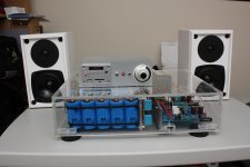
here is my nap140 with the tubeshunter kit and a few parts exchanged...
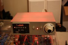
it is almost completed (finally). I built a B1 buffer (with MP3 player) for source/volumm control. i just need to get a real knob, and mount feet and add MP3 player faceplate. I will probably sand it the amp case (to make it opaque) like i did the B1.
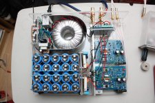
i know it looks like i went crazy with the capacitors but those screw caps are only 1400uf each (so 14,000uf per rail). I got them real cheap but they were bigger physically than i expected..
so right now i at 18 and 30mv DC offset and sounding good plugged into the B1 and my test speakers.
The only issue i have is when i have no cables connected i get a good bit of hum. if i just connect my cables the hum is almost gone and when i then plug the cables into the B1 the hum is gone (with or without power to the B1) All connected up there is just a little white noise only audible with my ear directly in front of the speaker.
So any hints on how to solve the hum?
thanks
it is almost completed (finally). I built a B1 buffer (with MP3 player) for source/volumm control. i just need to get a real knob, and mount feet and add MP3 player faceplate. I will probably sand it the amp case (to make it opaque) like i did the B1.
i know it looks like i went crazy with the capacitors but those screw caps are only 1400uf each (so 14,000uf per rail). I got them real cheap but they were bigger physically than i expected..
so right now i at 18 and 30mv DC offset and sounding good plugged into the B1 and my test speakers.
The only issue i have is when i have no cables connected i get a good bit of hum. if i just connect my cables the hum is almost gone and when i then plug the cables into the B1 the hum is gone (with or without power to the B1) All connected up there is just a little white noise only audible with my ear directly in front of the speaker.
So any hints on how to solve the hum?
thanks
Attachments
That is fabulous. A lot of people, including myself believe it's better to have lots of little caps rather than a couple of big ones. I suppose in the long term there is more chance of failure, but being new that wouldn't be a problem for a long time, if ever. I like the case and wiring also and the trany shield. Very professional. What did you use as a case? The earth problem doesn't matter if your going to use the B1, but would be better sorted. Could you not try lifting the signal from the star with a resistor? Well done!
thanks
I think the plastic is polycarbonate... I got the plastic from my work we were getting rid of a bunch of "splash shields" im a chemist... It cuts pretty easily on a table saw and glues up strong with CA glue. The trick is not to scratch it while you work with it. Since this stuff was not bought new it did not have a protective film. so it cam out alright as is but i planned to sand it opaque and add some leds in the case to give it a bit of a glow.
as far as the caps im not too worried about that because it should not happen anytime soon, they are 100v and rated for long life. For the most part i followed tnt-audio power supply suggestions including the filter circuts...
How about the line in gound resistor what knind of values should i try?
the B1 is a type of preamp designed by Nelson Pass (Pass Labs: Technical articles) there is also a forum devoted to his designs here. it is a pretty simple circuit so i did it without a board.
you an of course just use a stereo potentiometer for volume control.
I did not have any problems building it and it worked first try. but i swapped some parts including output transistors and now it doesnt seem as stable as original but im not sure because i didnt keep it stock for long... this is my first build of this type of amp so learning as i go a bit.
So any hints on how to solve the hum?
thanks
Hi,
Very nice looking amp!
About the hum, I noticed that your grounds are connected as supposed, so I don't believe it's a ground problem.
You can try to connect the star ground to earth, or to disconnect it from earth if it's already there.
Am I right that you are using some EMI/RMI filter built in your AC socket? If so, you may try to bypass it for test. I found that in audio this type of filters are causing more problems than they solve. I never succeeded in using one without hum problems. Mine had even a mechanical buzz in addition
") ... piece of expensive junk ...
... piece of expensive junk ...Regards
Thanks Ruwe,
Currently i am not grounded to earth. I will give that a quick try and and then test it without the AC filter socket. You are right thoses are exspensive. Fortunately i did not buy it. I took it from a retired instrument in the laboratory.
I think i am going to try a tip for the bias transistor because i am not happy with the amount of drift i am getting although both channels behave the same so far i have been using 2n5551. For exmple i thought i had both channels set at 7mv one day after plenty of warm up time and when i measured it the next day it was only around 4mv. This was measured a few minutes after i had been playing music at low levels...
So speaking of bias is there a preffered value im using toshiba 2sc5200 power transistor. So far i have been gong for 7mv but i thought i read 10 somewhere.
So speaking of bias is there a preffered value im using toshiba 2sc5200 power transistor. So far i have been gong for 7mv but i thought i read 10 somewhere.
Hi,
Well, try the earthing, but look at it on a system level. If you have another component (CD player, preamp) already connected to earth, probably attaching the power amp to earth will not change a thing or you'll create ground loops and have more troubles.
If you need stability in bias current you need to play with the value of the 27 ohms resistor above TR5. You can change it both ways to test the effects on bias stability. For example replace it with a 18 ohms, or 39 ohms. One of them should make the bias even more unstable, the other more likely will fix it. For sure you don't want a bias that rises with time though! Be careful with that. It's better to go towards underbias with time if you can't make it absolutely stable.
Are you saying 7 mV across one 0.22 resistor, or across both?
I don't know what is the best value, I try to keep mine in the lower recommended range - around 4-5 mV. To determine the best bias value, you'll have to test only the output stage circuit, without any negative feedback in order to define on oscilloscope where the crossover distortion disappears.
thanks for the input...
well i tried both ground to earth and removing ac filter plug and no change on the hum. So the good thing for now as long as i have the inputs plugged in it is fine.
As far as biasing... I checked it carefully. Disconneted speakers, inputs and let it warm up for 30mins and then set it for 6mv (across one 0.22ohm). I let it sit like this for 1 hour and it is stable. Maybe i will set it to 5mV instead today..
But here is why i thought i had a stability problem... The bias reading drops a couple of mV when i get my hands close to or touch the signal line ins on the boards. I dont know if this is normal but now i have been more carful where i place my hands during biasing and have two dvms hooked up the whole time.
im working on getting my hands on a scope.. just trying to justify a purchase here at work
But here is why i thought i had a stability problem... The bias reading drops a couple of mV when i get my hands close to or touch the signal line ins on the boards. I dont know if this is normal but now i have been more carful where i place my hands during biasing and have two dvms hooked up the whole time.
Hi,
Could be bad solder joint or component somewhere around TR5... Try cold spray if you have some handy. When you spray the suspected components one by one, you'll see big change once you hit the faulty one...
Or perhaps you have some sort of stability problem, mild oscillation when some conditions are met (like changing some capacitance with your hands close to the boards). These amps are famous for being unstable. Until recently Naim was recommending using them only with their proprietary cables, which are inductive (high characteristic impedance). After that they obviously fixed the stability problem and I even read somewhere that all speaker cables would work and not cause any issues.
...
Or perhaps you have some sort of stability problem, mild oscillation when some conditions are met (like changing some capacitance with your hands close to the boards). These amps are famous for being unstable. ..
Yes i have read on this forum how these amps are sensitive to oscillation...
Im afraid that is what is happening for me.
Sorry for the long post but here goes…
After more checking they are not as stable as I lead myself to believe. I managed to bias both boards to 6mV and they seemed stable for over 1 hour. The next day I checked thm and they were at ~2.5mV.
So here is the history…
I built and tested both boards with original parts. They both worked and biased fine. The thing is I never tested them at the same time.
What I changed
1. Swapped out sn5551 for bc546b (this helped reduce dc offset).
2. Removed the output 0.22ohm resistor and added a 12ohm with small inductor and changed the 10uf C1 for a bipolar (worked fine).
3. I put in mje15030 and mje15031 for the tip output transistors. I think I was getting oscillation when I did this. The bias would adjust up to about 3mV and then jump to 10mv or so. When I turned it down from there it would go to about 8mv and jump back down to 3mv. I changed the 39pf cap for a 47pf cap and this seemed to be the cure. The bias response was normal again…
The above was all tested powering only one board at a time.
So I did the mods to the second board and then hooked up both in final mounting configuration and now I realize its acting crazy. Plus I have the aforementioned hum with no source cables plugged in.
To repeat each board biases fine when only powering one of them. Also there is much less hum/buzz with no input cables plugged in with only one board powered.
When I power both boards I can adjust them each up to about 3mv and they behave as individuals. If I leave one at 3 mV and bring the second up to 6mV all is fine and stable. At this point there is no bias change depending on the placement of my hands to the boards. Now when I start to increase the bias on the 1st board when I get past about 3mV the second board also starts to increase. At the same time the bias values are now very sensitive to where I place my hands. If I keep playing with both I can eventually get a 6mv bias on both boards that can be stable. Whe i do this I think I am biasing in a state of oscillation because if I turn it off for a while and recheck I am nowhere near 6mV on each board even after letting warm up..
So Is it possible I have mild oscillation the whole time and it just gets worse with both board going?
I change Q5 from sn5551 to BC546b but no change. Should i try a tip41 here?
I can get the ZTX653/753 could these help? (note - Avondale combo is MJE outputs with ztx)
I don’t really feel like pulling out the mje output transistors and putting the tips back in before i try ztx but i might.
comments and suggestion welcome,
thanks
Hi,
Very interesting problem ... and I'm sure quite irritating.
What I am thinking is that the only common points between the two channels are the supply rails and the ground. That's the only thing that can make the difference, as described by you, between one or both channels working. So, taking a look at your pictures I was wondering where physically is connected the transformer centre tap. I can't see it at the star ground and I have the feeling that it's connected on the other side (left side) of the capacitor bank.
Capacitor bank is a nice thing, but the problem that occurs is that it ruins to some point the idea of star ground. Ideally, each capacitor should have separate wire going directly to the star ground. In your configuration going for that is huge complication and I would only suggest to move the traf's cente tap wire to the star ground as a first measure. I don't really believe it will fix the problem, but who knows.
As a second measure I would suggest to try different driver transistors. Something with higher gain (to avoid loading the VAS stage too much). I'm using MJE243/253. MJE15030/31 are quite similar, but I haven't tried them. I'd tried other types though, and some of them in fact gave oscillations.
I believe that some BD139/140 would also work fine (not tested though).
A friend of mine is running this amp with the TIP transistors from the kit and the amp is stable.
You can certainly kill the oscillations by increasing again the VAS capacitor. You did that from 39 to 47pF. You can try 56 or 68pF, but generally this capacitor should stay as small as possible, because the bigger the value, the lower the open loop gain. At some point it's possible to wreck the sound of this amp by using bigger capacitor in the VAS. A matter of balance...
IMO, Q5 is harmless, you can use whatever transistor type you want. I use MJE243, but have tried 2SC2240, 2N5551 and BC550 without change in behaviour of the amp. This is a simple Vbe multiplier and is not prone to oscillations.
I hope some of this may help. I don't have anything else useful at this point.
Regards.
I think you have a point Greg. The Naim's do not look like the case is used as a heat sink (unlike Cyrus for instance, where the output transistors are bolted onto the finned case), but although there is a heatsink inside the case, the whole thing is aluminium and therefore a heatsink. You do need a decent heatsink for these amps. I would like to say that some of these amps that have evolved from this thread are fantastic (Dave S, Blistard, Ciariello, etc). It would be nice to see some more pics. Did we decide which board was better. I havn't been paying attention. Regards Barry
Hello Barry, I will taken some new pictures later today.
I have removed the pre-amp out of this amplifier and replaced it with a Pass B1 in a seperate case. I also slightly modded the "NAP140" board with some extra decoupling for the transistors and filmcap-bypass for NFB. It didn't do much for the sound though. I still think the bass is among the best I have ever heard (bass on "three days" - Janes Addiction), but it doesn't convince me on higher volumes. This might just be because of the limited power. On higher volumes it gets harsh.
The 2 toroids of 140 VA each must be enough. Could the other PSU-parts be to blame, or is this just the way this design behaves?
- Home
- Amplifiers
- Solid State
- NAP-140 Clone Amp Kit on eBay