Hello
Avondale wrote max 50V rail at 8 Ohms.
I tried 39-0-39V transformer to me didn't work. It was very unstable.
The Avondale kit much better than the Ebay kit.
I have a set Ebay kit $20 if someone need it.
Actually I tested at lest 4 different type of design.
The next I want to test with the same transistors what Chrome bumper use.
These amplifier is very sensitive even if you change a PC of wire! If you want good sound you have to spend a lot of time , to test different parts, wires etc.
Greetings
He looked like your kit. If all is good buy. Send a photo toHello
Please not be fooled by the look of the amplifier !
Those are Welwyn high quality resistors! Surly the capacitors can be upgraded Elna Silmic or so.
I have the Sanken (original) and those driver, I want to give a try.
My NCC200 sound far better than the Ebay kit.
Actually still have that kit, need some capacitors at the protection, I took the out.
I can sell it $15 plus shipping a pair if someone interested. I paid $65 on that time plus shipping.
I can provide picture upon interest.
Greetings Gabor
yuragruzz@gmail.com
I have not changed anything. These transistors in my kit.Hi,
is there much of a difference betweenthe avondale pcb's and the gigaworks kit?
does the gigaworks np140 kit stock kit sound good or requires lot of component replacement or modification. are they using fake transistors(?)
thanks.
Was comparing the H-140 with the NCC200 and thought of doing the following mods:
1) Add the two 100nF/0.1uF 50V poly caps that are missing in parallel with the two 100uF elec caps under the board.
2) Add the missing 15 ohm 2W output resistor. Wire in series with speaker binding post cable.
3) Replace the 3K ohm resistor for 2.7K.
4) Replace the BC550 transistors for BC546.
5) Replace the 56pF cap with 47pF mica.
6) Replace the 68uF cap with 68uF mica.
7) Replace the 220pF caps with 220pF polystyrene.
8) Replace the 470pF caps with 470pF polystyrene.
9) Replace the C2240 with ZTX653.
10) Replace the A1145 with ZTX753.
11) Replace ? uF cap with 47uF wet tant.
12) Add 1K ohm resistor between 47uF wet tant and BC546. Have to cut a track and add under the board.
13) Replace TIP41 with MJE15030 NPN.
14) Replace TIP42 with MJE15031 PNP.
15) Replace 2SC5200 with MJ15003.
Which do you think are worth doing? Which ones did you do?
Thanks,
Philippe
Hi, Hopefully you can help me
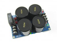
I bought some preassembled NAP140C boards from eB*y (They are blue with Sanken 3858 outputs) And 2 power supply boards with 35a rectifiers & 4 10000uf "Nover" caps... I'm sure you know the ones...Also a pair of 300va 25v transformers.
Wired it all up today and it fired up fine with -70mv dc offset & set the bias at 5mv. connected a pair of speakers & sound lasts for around 3-4 seconds before cutting out, dead. Noticed the green led's on the power supply boards fade out just before it dies. I have found that removing the speaker return wires from ground stops the problem but thats hardly helpful
Tried all different grounding schemes & nothing seems to work so I'm here for any ideas what might be at fault.
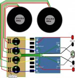
Many thanks. PS. the wiring diagram I followed is attached.
I bought some preassembled NAP140C boards from eB*y (They are blue with Sanken 3858 outputs) And 2 power supply boards with 35a rectifiers & 4 10000uf "Nover" caps... I'm sure you know the ones...Also a pair of 300va 25v transformers.
Wired it all up today and it fired up fine with -70mv dc offset & set the bias at 5mv. connected a pair of speakers & sound lasts for around 3-4 seconds before cutting out, dead. Noticed the green led's on the power supply boards fade out just before it dies. I have found that removing the speaker return wires from ground stops the problem but thats hardly helpful
Tried all different grounding schemes & nothing seems to work so I'm here for any ideas what might be at fault.
Many thanks. PS. the wiring diagram I followed is attached.
Attachments
Last edited:
Did you try running separate power grounds from each PSU-board to each amp board....?
Yep, I tried that first but no different... I'm going to rewire the ground cables now anyway & see what happens - Im sure its a grounding issue of some sort
Is this the board that you have to wire a "jumper" between SG & GND ?
Best regards.
Back again!
Fully rebuilt one channel on the workbench & re-wired it but still the same. However I have discovored that when the green led goes out & the speaker output stops, the bias drops from 7mv down to 0.2mv but the power supply maintains 34vdc +&- into the amplifier board
Pulling my hair out now with this
Hi, I seem sto have the same boards as you do with the 2sc3858 o/p transistors on pre-built boards. Connected them up through a variac and immediately found very high dc on output which simply follows the negative supply rail as I adjust the variac. I notice the earth point neat the o/p transistors simply feeds to a cap and is not connected to the small signal earth point. Both boards do the same thing.
What did you mean 'I had wired the speaker to GND - changed it to DC 0V' ?
What did you mean 'I had wired the speaker to GND - changed it to DC 0V' ?
Hi, I seem sto have the same boards as you do with the 2sc3858 o/p transistors on pre-built boards. Connected them up through a variac and immediately found very high dc on output which simply follows the negative supply rail as I adjust the variac. I notice the earth point neat the o/p transistors simply feeds to a cap and is not connected to the small signal earth point. Both boards do the same thing.
What did you mean 'I had wired the speaker to GND - changed it to DC 0V' ?
You need to connect both SG & GND to your main earth point. Then you connect the 0v speaker terminals to negative rail on your power supply cap bank. Thats what got them working for me. Beforehand they would work for a few seconds with DC on the outputs before cutting out.
I think Istari knight is referring to the negative terminal of the + rail electrolytics, which is common with the + terminal of the negative rail electrolytics and that is star earth (or "main earth point" or as Randy Slone says it, "quality ground") The PCB allows for these separate connections which are easily ignored without a full schematic. A pity that, with many Ebay products.
If you like, there will be several critical ground points in power amplifier circuits, all electrically connected but in such a way that there is minimal influence of earth currents in one section on the others and hence lowest possible hum and noise.
Ideally all electrolytics, power supply common and signal return earths are connected at the one point only, that "star ground". Read any good audio text or any of several threads treating amp. basics here on Forum. Even Google "star ground" or similar.
Thanks Ian,
I am aware of star grounding - it reduces mains humm, etc but won't account for the dc on the output. There is a ground point near the o/p transistors which only feeds a cap directly and another one for small signals at the input. I assumed that each should be connected to the star grounding point which also connects to the 0V line between the caps as you mention and is the centre between +40V and -40V. Whether I then connect the one side of the speaker to the to the star earth, the grounds on the board or directly to the 0V point on the caps, its all at the same voltage and won't account for the dc on the amp outputs - moving the connecting point will affect humm but not the voltages. I could not understand connecting the speaker to the negative rail and amp output. Connecting to 0V on the caps or at the star earth is basically the same thing - unless star earth was not connected to 0V at the caps - so why did his amp suddenly work?
I am aware of star grounding - it reduces mains humm, etc but won't account for the dc on the output. There is a ground point near the o/p transistors which only feeds a cap directly and another one for small signals at the input. I assumed that each should be connected to the star grounding point which also connects to the 0V line between the caps as you mention and is the centre between +40V and -40V. Whether I then connect the one side of the speaker to the to the star earth, the grounds on the board or directly to the 0V point on the caps, its all at the same voltage and won't account for the dc on the amp outputs - moving the connecting point will affect humm but not the voltages. I could not understand connecting the speaker to the negative rail and amp output. Connecting to 0V on the caps or at the star earth is basically the same thing - unless star earth was not connected to 0V at the caps - so why did his amp suddenly work?
prebuilt NAP140 clone module
About 18 months ago I built built an ncc200 amplifier using the “genuine” PCBs supplied by Avondale and faithfully following the Avondale parts list. That had been my first serious attempt at building a moderately complicated piece of electronic equipment. I was both surprised and happy that it worked perfectly from first switch on and I have been really delighted with the sound quality ever since.
My rationale for not buying a Chinese clone then was that Les Wolstenholme, the designer of the ncc200, had spent years refining his design while working with and servicing Naim equipment and I was happy to pay a premium to benefit from his experience.
However I was always curious about how good these clones were and ultimately decided to a pair prebuilt Naim NAP140 modules just to hear what they sound like.
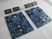
When I first saw them I was impressed by the soldering and build quality. However the quality of the transistors (including the Sanken output ones) looked dodgy to me and I suspect that they are not genuine.
The only changes I made to the prebuilt boards were to:
• replace 2 of the transistors, one a with a ztx753 and another with a ztx653 because I could not find any datasheets for the those particular ones that were on the board. This involved some bending of the legs of the ztx ones because the pinouts were different
• replace the 10uf and the two 68uf caps with some tantalums and solid alumium ones that I had as spares.
• disable the output protection circuit by disconnecting the 2 1N4148s near TR7 and TR8
• add an inductor in series with the amp output.
I adjusted the bias to 4.5mv across the 0.22 ohm emitter resistor and measured the dc offset at aroung 10mv on each module which was fine and fired it up today.
I was relieved and happy that it actually worked and my initial impression was that it sounded not bad at all. After listening to various bits of music that I was familiar with I thought that both the balance and detail were good but ultimately I realised that I wasn’t knocked out by the sound. I had listened to several Naim amplifiers in the past and had always very impressed by them but I didn’t get the same reaction when listening to this one. My wife's reaction was that the sound wasn’t bad but it wasn’t that great either.
I then fired up the Ncc200 and immediately was impressed about how good it sounded-detailed very full and rich compared to the clone.
On reflection I was disappointed with the clone and was somewhat surprised that in spite of being a fairly accurate copy of the Naim circuit the sound was just so ordinary. If I didn't have the ncc200 to compare with I just don't know whether I would have been content with the clone.
Out of curiousity I will persevere with a few more changes by replacing the driver and output transistors with known genuine quality parts just to see if that makes any difference.
Also I’m intrigued that at least one person claims to have immeasurably improved/transformed the sound by replacing the 0.22 ohm output resistor with (I think) a 10ohm one. I might try that as well.
About 18 months ago I built built an ncc200 amplifier using the “genuine” PCBs supplied by Avondale and faithfully following the Avondale parts list. That had been my first serious attempt at building a moderately complicated piece of electronic equipment. I was both surprised and happy that it worked perfectly from first switch on and I have been really delighted with the sound quality ever since.
My rationale for not buying a Chinese clone then was that Les Wolstenholme, the designer of the ncc200, had spent years refining his design while working with and servicing Naim equipment and I was happy to pay a premium to benefit from his experience.
However I was always curious about how good these clones were and ultimately decided to a pair prebuilt Naim NAP140 modules just to hear what they sound like.
When I first saw them I was impressed by the soldering and build quality. However the quality of the transistors (including the Sanken output ones) looked dodgy to me and I suspect that they are not genuine.
The only changes I made to the prebuilt boards were to:
• replace 2 of the transistors, one a with a ztx753 and another with a ztx653 because I could not find any datasheets for the those particular ones that were on the board. This involved some bending of the legs of the ztx ones because the pinouts were different
• replace the 10uf and the two 68uf caps with some tantalums and solid alumium ones that I had as spares.
• disable the output protection circuit by disconnecting the 2 1N4148s near TR7 and TR8
• add an inductor in series with the amp output.
I adjusted the bias to 4.5mv across the 0.22 ohm emitter resistor and measured the dc offset at aroung 10mv on each module which was fine and fired it up today.
I was relieved and happy that it actually worked and my initial impression was that it sounded not bad at all. After listening to various bits of music that I was familiar with I thought that both the balance and detail were good but ultimately I realised that I wasn’t knocked out by the sound. I had listened to several Naim amplifiers in the past and had always very impressed by them but I didn’t get the same reaction when listening to this one. My wife's reaction was that the sound wasn’t bad but it wasn’t that great either.
I then fired up the Ncc200 and immediately was impressed about how good it sounded-detailed very full and rich compared to the clone.
On reflection I was disappointed with the clone and was somewhat surprised that in spite of being a fairly accurate copy of the Naim circuit the sound was just so ordinary. If I didn't have the ncc200 to compare with I just don't know whether I would have been content with the clone.
Out of curiousity I will persevere with a few more changes by replacing the driver and output transistors with known genuine quality parts just to see if that makes any difference.
Also I’m intrigued that at least one person claims to have immeasurably improved/transformed the sound by replacing the 0.22 ohm output resistor with (I think) a 10ohm one. I might try that as well.
- Home
- Amplifiers
- Solid State
- NAP-140 Clone Amp Kit on eBay