Hi ciariello,
First check the current through the 68 ohms resistor in the emitter of ZTX 653. If it is about 8.5-10 mA you're good.
If your bias current is not adjustable most likely the Vbe multiplier doesn't work (the transistor between the ZTX653 and ZTX753). Check the pin orientation and the resistor values around. The voltage for the right bias current is about 2.35-2.38V between the collector of ZTX653 and ZTX753.
One of your channels has DC offset problem. Probably something at the inputs resistors or the feedback resistors. Check the values of the resistors.
... And get rid of the fakes, but I don't believe they are causing the problems.
i replaced the MJ15003 with genuine ONSemi.
i replaced the MJE15030/31 with genuine ONSemi.
i replaced the BC550/2N5551 (Q1-Q2-Q5) with genuine Toshiba 2SC2240
i replaced the 220-330-470pF capacitor with film capacitor Wima (i can't find 39pF)
the DC offsets are changed.
On channel 1 the dc offset value starts from 20mV and increases in proportion to the temperature of the ZTX until 35-37 mV.
On the other channel the dc offset starts from -120mV and increase until 0mV and over in proportion to the temperature of the ZTX.
i think (LIKE YOU )the fakes transistors wasn't the overheat cause..
It is JUST another strait "blameless" , just another flavor.....what is the big deal. This is the "monday" amp , sym for tuesday ,blame es for thursday, leech for friday. Unless there is something REALLY wrong , an offset of under 10 Mv will be typical ... at least go through 10 differential pairs to find 2 similar ones !! I run this circuit at 6mA , never hot ... just "luke warm" ...
OS
OS
Last edited:
i readed the current value on both 68 resistors ...we are around 10-11 mA but the voltage between the ztx collectors is 1.995 on channel 1 and 2.018 on hte other.
Hi,
10-11mA is a little bit on the high side, but is acceptable. Both ZTX will be hot, 60C is well expected.
When you turn the bias setting pot, does the voltage between the collectors change? This means that your current in power transistors is also changing. Both changes must be related.
Your measured voltage looks slightly low to me, but I'm using different transistors. Is your current in the power transistors normal (around 25 mA) with this voltage?
The DC offset is not much related to the hot transistors. It's fixed by the differential pair at the input. If it is shifting you should look there for faults.
hi and thanks for your reply.when i try to set (on both channel ) the bias they don't change and became ALWAYS 25mA.Now i powered ON the ampli and I connected 2 JBL CONTROL 5 (4 ohm) with a NAD 502 CD player to check if everything works well ... and I must say that even with these speakers (not great but better to sacrifice them!) sounds really good and " appears "that the ZTX become less warm.... I'll keep everything a little less in practice and then I will tell you the changes. Thank you all for your help
hi and thanks for your reply.when i try to set (on both channel ) the bias they don't change and became ALWAYS 25mA.Now i powered ON the ampli and I connected 2 JBL CONTROL 5 (4 ohm) with a NAD 502 CD player to check if everything works well ... and I must say that even with these speakers (not great but better to sacrifice them!) sounds really good and " appears "that the ZTX become less warm.... I'll keep everything a little less in practice and then I will tell you the changes. Thank you all for your help
Hi,
Well, then the Vbe multiplier doesn't work properly.
Check if the transistor is connected correctly, according to schematic, and that the board labels correspond to the actual pin-out of the transistor. Sometimes there are many errors on these boards.
Also check that the trimmer works, by measuring changing resistance between its pins when you turn it. The voltage between the ZTX collectors must change when you turn the trimmer, as well the bias current.
Start bias current adjustment always with the trimmer turned for max resistance, usually counter-clockwise on most boards. Also have in mind these trimmers are multi-turn, so to see a change you have to turn it more than, let's say, few turns. Then it suddenly gets quite sensitive and current change is significant.
The DC offset should be very stable. It doesn't change at all, and is usually somewhere in 5-30 mV range. It's not affected by the load/no load output.
Do you have an oscilloscope? It would be nice to check if that DC offset is actually a DC. It could be some mild high frequency oscillation that your multimeter sees as DC.
Regards
I did several tests / readings with an oscilloscope and there are no self-oscillations on the outputs of the amplifier but it is DC.
Finally I checked all the connections and pinout of the transistors and they are all correct (datasheets and schematic diagram in hand).
multi-turn potentiometers works well by changing the value.
Conclusion ... the amp sounds great shorting the inputs is VERY VERY VERY quiet, the ZTX heat but the temperature is still around 60 ° C.... "BUT " the bias is still not able to be changed and remains on 25mA.
I think that they should be to leave everything as is and enjoy weeks of work ...
Thanks to all.
Hello,
I am currently putting together two monoblocks with the naimclone boards from ebay aswell. I trashed the components that came with the kit and replaced them with the parts mentioned in the NC220 schematic posted somewhere in this thread aswell.
Output trannies are NTE-58 replacements from ON Semi
On the NC220 schematic both Q7 and Q8 and C3 and C4 are not mentioned, with what can they be replaced since Q1 - Q6 are different now aswell?
(Q1-Q2-Q3 are BC546, Q4 is ZTX753, Q5 is 2n5551, Q6 is ZTX653, Q10 is MJE15030 and Q11 is the MJE15031)
Could someone push me in the right direction?
Q1-Q2-Q3 are BC546, Q4 is ZTX753, Q5 is 2n5551, Q6 is ZTX653, Q10 is MJE15030 and Q11 is the MJE15031
Hi,
Looks very good to me. I don't have experience with these drivers and power transistors though.
Just an idea: Buy BC546B or C for the input stage. High gain transistors are beneficial in this position. Or you can pick and match them by hand. hfe of >300 is best, IMO.
On the NC220 schematic both Q7 and Q8 and C3 and C4 are not mentioned, with what can they be replaced since Q1 - Q6 are different now aswell?
These are part of the protection circuit that is not used in most kits. If you want it, use C3,C4 10uF/50V and Q7,Q8 BC546/556 or 2n5551/2N5401. The transistor choice is not critical, this thing is supposed to stay normally off.
Last edited:
")
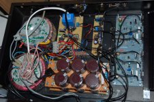
It's alive!
Just "finished" the build of my NAP-140 clone. Still have some tidying-up to do, but it works just fine.
2 transformers 30-0-30 120 VA feeding 6x4700 mF + 1 mF film / channel all connected with 1,5 mm copper to the NAP-clones (hifidiy.net)
Preamp is a simple single op-amp design (OP-177) with 2x amplification and a seperate power supply (78/7915) connected to the NAP with very inexpensive wire and a downright cheap pot.
Speakers are connected via a turn-on delay, but I think I need to add a fuse in the ground-line.
Of course these things are never finished, but what would you advise as the next step to take? (sound-quality-wise)
Attachments
I keep seeing these referred to as NAP140 clones, when in fact they are clones (and not 100% accurate at that) of the Avondale NCC200 amp boards.
If you want to clone the NAP140 I suggest downloading every picture of the NAP140 or 180 circuit boards you can find on the net and a schematic and alter the necessary components on the Gigaworks boards. It's not too hard to do (I did it once though haven't got the relevant docs any longer alas, though could post photos of my boards) and does get you one step closer to that addictive Naim sound...
- John
I keep seeing these referred to as NAP140 clones, when in fact they are clones (and not 100% accurate at that) of the Avondale NCC200 amp boards.
- John
You are absolutely correct. It has been brought up a number of times in this thread. The amp I build is not a NAP-140 clone, but it is an amp that is reffered to as beeing a NAP-140 clone. So I thought that the name NAP-140 clone describes the amp I build close enough for most people here to understand. It is not my intention to build a "real" NAP-140 anyway. After this I will probably move on to a Pass-amp.
hi,
i finally got around to finishing my tubeshunter boards... they seem to be working properly with a low dc offset after swapping q1 q2 for a set of bc546b with a 10% mismatch in hfe... i am just finishing up a p2p B1 to go with it so i haven't done listening yet on anything but cheap test speaker..
My question is has anyone tried the output transistor decoupling mod mentioned as a noticeable improvement for naim amps at Modifying Naim Audio power amplifiers ?
Hi, I want to use a speaker protection circuit. I found one on ebay.
Speaker Protection Module -- Stereo Type Two Channels - eBay (item 300515253360 end time Feb-13-11 13:07:33 PST)
What do you think about this module? Any suggestions for other?
Speaker Protection Module -- Stereo Type Two Channels - eBay (item 300515253360 end time Feb-13-11 13:07:33 PST)
What do you think about this module? Any suggestions for other?
Voltera,
I'm using this one:
QKits Electronic Kits: K4700, Two Channel Speaker Protection Kit 220VAC
Flappytango,
I've tried the the output transistor decoupling and didn't like it. Nothing wrong looking with the scope, but the sound became dull and I removed it. There was a feeling of "too much" bass. A friend of mine reported the same.
I'm afraid though that we didn't do it properly - the return from the caps of each channel should be tied together and then with a single wire sent directly to the star ground. The way I did it was both caps connected together to the speaker GND output on the board.
May be you should try it, but IMO, this amp benefits more than anything else from wiring with heavier gauges and higher quality of the reservoir capacitors.
Regards
Ruwe,
Thanks maybe ill skip it for now and wait untill i order some parts and give it a try then.
Volterra,
I am using this kit.
Speaker protection circuit stereo kit 30A protection ! - eBay (item 220725085071 end time Feb-13-11 07:21:18 PST)
It is inexspensive and seems to work, athough i cant guarantee the level of protection it gives. It has a long turn on delay time ~12 seconds. I might try to modify some component values to shorten the time. So it at least offers turn on dealy and speaker disconnect at power off.
- Home
- Amplifiers
- Solid State
- NAP-140 Clone Amp Kit on eBay