How do you ensure current sharing between paralleled diodes?Preferred solution to that of the trivial and cheap Graetz Bridge, because by installing one or more diodes (perhaps fast type and still much better than the normal Graetz Bridge) in parallel for each branch, you can significantly reduce the internal resistance of the entire stage of power supply, bringing our power supply to the ideal Theoretical Voltage Generator.
How does a diode's forward resistance compare with the transformer's secondary resistance?
Why?An aspect punctually ignored also in expensive and prestigious amplifiers and that repays with a sound clearly more seductive and realistic.
If dual secondary, why not one bridge for positive supply and one bridge for negative supply?
With the premises made, absolutely not!
And the reason is always linked to the fact that if we want our power supply stage to be as close as possible to the ideal Voltage Generator, we must reduce and certainly not increase its internal resistance.
And in the case of a bridge with a Graetz bridge instead of a single diode (or even more than one in parallel) we go exactly to double the internal resistance of our power supply (apart from the reactance of the transformer and the filter capacitors).
But just to stimulate your reflection I add:
We all know that a normal Silicon diode, when in full conduction, has a voltage drop always equal to about 0.7 Volts.
But if it is delivering 5 Ampere it will have an internal resistance of 0.14 Ohm but if it is delivering only 0.005 Ampere, it will have 140 Ohm.
But from the point of view of the correct and fundamental coupling of Impedance (on which depends the entire frequency bandwidth) how will our precious amplification stage composed of: input differential, VAS stage, pilot stage and power amps react to this continuous and unpredictable variation of Input Impedance?
To posterity the arduous answer (in fact, with a correct design approach very easy or even obvious)!!
Diodes in parallel is new concept to me... How is that working? Isn't one of them just sitting there doing nothing, unless sharing is ensured with small series resistors?
Diodes in series is a popular technique, but I've never seen them used in parallel...
The answer and the theoretical premises I indicated in the previous post.
However, I would like to add that despite the improvement of increasingly refined production technologies, in reality it is inconvenient to use more conventional diodes in paralel, because even if only slightly, they could have different intervention times at the time of "conduction" as soon as the threshold voltage is exceeded.
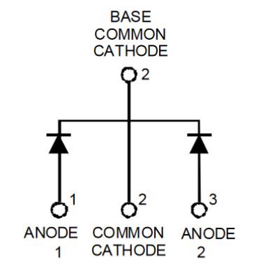
Much better then to use the so-called double diodes, which are made on the same wafer of doped silicon.
Below is the example of an Ultra Fast type and that among the many I have been using for years, in my constructions, the MUR2020CT:
Last edited:
How do you ensure current sharing between paralleled diodes?
How does a diode's forward resistance compare with the transformer's secondary resistance?
Why?
I hope I've been able to answer your questions as well..
I can only add that given that during the dynamic operation of an amplifier, the power supply stage is an integral part of the amplifier itself and is entirely affected by the passage of our precious musical signal, it is essential an approach that goes far beyond the banal circuits, paying extreme attention to even the most seemingly insignificant aspects, if you want to get an audio electronics capable of making a difference compared to the other.
Last edited:
We all know that a normal Silicon diode, when in full conduction, has a voltage drop always equal to about 0.7 Volts.
But if it is delivering 5 Ampere it will have an internal resistance of 0.14 Ohm but if it is delivering only 0.005 Ampere, it will have 140 Ohm.
But from the point of view of the correct and fundamental coupling of Impedance (on which depends the entire frequency bandwidth) how will our precious amplification stage composed of: input differential, VAS stage, pilot stage and power amps react to this continuous and unpredictable variation of Input Impedance?
[/LEFT]
I don't think this is the correct way to determine a diode's internal resistance
Two diodes in parallel, in the best case scenario, will turn on at different times. So you'll have even more switch-on/switch-off disturbance, even if you use some fancy dual diodes (which, by the way, are also not meant for use in parallel).
In general, of all these theories so far, I agree only that the power supply maters a lot for the sound quality of any amplifier...
I suggest we return to the Naim topic.
Last edited:
Not really. Diodes are not resistors. Even if they share the current perfectly their non-linearity will counter-act their conductivity as each will conduct only half the current. The winding resistances of the transformer will be of the same order too. I’m not sure what your reason is for fast recovery diodes either.I hope I've been able to answer your questions as well..
The larger the caps the less time the transformer has to recharge the caps. Current = charge / time. The less time the higher the transformer current.
I read on PFM people recapping their old Naims and taking advantage of modern capacitor size efficiency to fit 50% or more capacitance. No mention of the transformer.
I read on PFM people recapping their old Naims and taking advantage of modern capacitor size efficiency to fit 50% or more capacitance. No mention of the transformer.
on my side, I finally found a good case to mount my next Naim.
a customer brought me a LFD zero MK3 to repair, which I did
after many disappointments.
then the customer brings me back barely 2 months later with the two channels hs.
I'm surprised, I ask him to go home to see the rest of the equipment and I quickly understood, not far from 30M HP cable with two pairs of speakers and a speaker selector has $ 10 on aliexpress.
the amp was so hot that the tracks on the pcb have disappeared.
I declared definitively dead and I came to the client my audio Innovation Alto Mk1 and the customer gave me his lfd which is built all aluminum of very good quality.
I'm not sure I follow what caused the LFB amplifier failures, huggygood. What is an HP cable and how did it cause the amplifier to overheat? Surely the 2 pairs of speakers were used alternately rather than in parallel.
Agreed though, a speaker switch from Aliexpress or Ebay etc. could be anything from 1A to 10A rated, as their offers never specify the ratings of components unless it is printed on the device. Buyers then have only appearance and price to make their choice from and that usually ends badly with any type of power switching device.
Agreed though, a speaker switch from Aliexpress or Ebay etc. could be anything from 1A to 10A rated, as their offers never specify the ratings of components unless it is printed on the device. Buyers then have only appearance and price to make their choice from and that usually ends badly with any type of power switching device.
try to run an LFD with 30M cable, a Chinese HP switch, realistic sound level, you'll see how long it will take before committing suicide.
I tried it at home with a pioneer A656, it was barely defective half the potentiometer.
the lfd held as long as he could, but was too much for him.
I made him a custom HP switch with relays and without pcb, just wires.
it's a pity, I threw the switch, I could have made you a picture of the interior, it was to die of laughter.
OK, I get it . 30M of speaker cable is a bad idea with most domestic amplifiers. I have also seen a few, including an early Naim, that were burnt out by fitting long cables. One guy even coiled up the unused length on the reel and then the cable got hot too before the smell of smoke ended the party.
. 30M of speaker cable is a bad idea with most domestic amplifiers. I have also seen a few, including an early Naim, that were burnt out by fitting long cables. One guy even coiled up the unused length on the reel and then the cable got hot too before the smell of smoke ended the party.- Home
- Amplifiers
- Solid State
- NAP-140 Clone Amp Kit on eBay