Any idea if the Toroidy Supreme is actually any different to the Toroidy Audio grade in terms of core and windings? Or is it the same thing in a nice case for double the price?
Unfortunately Toroidy don't seem to publish any figures for regulation, so it's hard to work out how good they really are. They also seem remarkably compact compared to the same VA rating from Canterbury Windings.
Apart from their attractive appearance and a slightly larger magnetic core than the Supreme Series, they are essentially identical and both have an electrical grounding shield between the primary and secondary windings.
I have always used both types with great satisfaction, but the Audio Grade series is unbeatable in terms of value for money.
I also used a Canterbury Windings on one occasion, I think I remember the 500VA, but I remember that the size and weight were basically identical to the Toroidy Lachowski or even a little smaller.
Last edited:
When is a real transformer not an ideal transformer?
- capacitance: inter-winding, winding to core, winding to shields, between loops of the same winding
- energy losses: winding resistance, core eddy currents & hysteresis, vibration, radiation, external eddy currents
- reactance: leakage inductance
- core flux non-linearity and saturation
- electromagnetic interference from external sources
+1 Right!
And this only if we talk about power transformers that work at a maximum frequency of 50/60 Hertz.
Then in the case of audio output transformers and interstage and/or impedance coupling, having to work with acceptable Harmonic Distortion up to 20.000 Hz and much more, the importance of complex geometries and alternating "layer" winding techniques comes into play.
And here the technique almost gives way to mastery and art!
+1 Right!
Then in the case of audio output transformers and interstage and/or impedance coupling, having to work with acceptable Harmonic Distortion up to 20.000 Hz and much more, the importance of complex geometries and alternating "layer" winding techniques comes into play.
And here the technique almost gives way to mastery and art!
I think that the techniques are well established and very clear as a theory. The problem is that it's not easy to make an output transformer in a way that won't cost +1000$. So, the art is in the way the manufacturers cheat to make them "almost good", but cheaper
")
So what calculation should be used to choose the right sized capacitors?Very often we tend to exaggerate both in the number of capacitors but also in the total capacity, not correctly sized and calculated.
Or at least, what factors should be part of such a formula?
As soon as I can, I sketch the detailed calculation procedure and place it in the thread. It's relatively simple but it's important to set the premises well that I want to explain clearly.
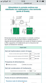
But in the meantime I send a link (in Italian but easily understandable) that allows the rapid determination of the filtering capacity of an electrical power stage that with sufficient reliability indicates the correct value.
The value you get is a little oversized (10/15 %), but much depends of course on the characteristics of Impedance of the speakers and the normal listening volumes:
Alimentatore in corrente continua non stabilizzato con raddrizzatore a 1 semionda
Last edited:
In general, the known and most common calculation approaches are all addressed to the containment of the filtering Ripple, but very rarely pay equal attention to the determination of the correct Capacitance as a function of the load absorption characteristics (speakers) both in static mode with a constant sinusoidal signal and even less in dynamic impulsive mode.
And the result is usually always an exaggerated oversizing that makes the sound "swollen" and poorly articulated and fast on the mid-bass, to be drawn from the quality of the capacitors used.
And the result is usually always an exaggerated oversizing that makes the sound "swollen" and poorly articulated and fast on the mid-bass.
But in the meantime I send a link (in Italian but easily understandable) that allows the rapid determination of the filtering capacity of an electrical power stage that with sufficient reliability indicates the correct value.
The value you get is a little oversized (10/15 %), but much depends of course on the characteristics of Impedance of the speakers and the normal listening volumes:
Alimentatore in corrente continua non stabilizzato con raddrizzatore a 1 semionda
I just tried the calculator but it does not take into account a functioning class A or class Ab.
I think after having done some tests that for AB it seems to be a match.
this for exemple :
Parametri di cavi schermati coassiali o linee di trasmissione concentriche.
Parametri di cavi schermati coassiali o linee di trasmissione concentriche.
I put numbers in for the 250DR. I halved the VA since the transformer has to feed two channels. With two 10000uF caps in series the Naim’s model equivalent is 5000uF. The model recommends 1500uF.
I wonder how the model works.
I wonder how the model works.
Attachments
I put numbers in for the 250DR. I halved the VA since the transformer has to feed two channels. With two 10000uF caps in series the Naim’s model equivalent is 5000uF. The model recommends 1500uF.
I wonder how the model works.
Why did you set up 60 Volts?
I estimated the Naim power rails to be about +-42Vdc, a differential of 84Vdc, which I think requires an ac differential of 60Vrms.Why did you set up 60 Volts?
The considerations are correct, but with the Naim, being in the case of an amplifier powered by two power rails (Positive and Negative), what the program asks you to indicate in the initial box is simply the effective value of the AC voltage output from the two single secondary transformers of the power supply.
That is, if we want a 42 Volt DC supply voltage, you must indicate an AC voltage of 30 Volts (42 : 1,414).
And the correct power to be indicated in the case of a single power transformer for both channels, for the same reasons as above, is not 250 VA, but 125 VA.
That is, if we want a 42 Volt DC supply voltage, you must indicate an AC voltage of 30 Volts (42 : 1,414).
And the correct power to be indicated in the case of a single power transformer for both channels, for the same reasons as above, is not 250 VA, but 125 VA.
Therefore, if the values described above are set correctly, what the simulation program will give is not the analytical value, but rather the available value of the normal commercial capacitors (6800 uF), rounded up or down.
Obviously, in the case of a stereo amplifier, this value must be multiplied by two.
Obviously, in the case of a stereo amplifier, this value must be multiplied by two.
Last edited:
I think that the calculator just assumes that the relatively high level of ripple at 80% of the power rating is an acceptable amount. Some folk will disagree strongly with that, count on it.
In reference to any of Naim's 250 models, power supply regulation completely changes the relationship between supply and load - we are now examining the response of the linear regulators since any dynamic influence of the rectifier smoothing caps is virtually isolated from the power amplifier.
In reference to any of Naim's 250 models, power supply regulation completely changes the relationship between supply and load - we are now examining the response of the linear regulators since any dynamic influence of the rectifier smoothing caps is virtually isolated from the power amplifier.
But is it completely isolated by the regulator?
A transformer with a single rectifier diode reminds me of a two-stroke petrol engine. Once per mains cycle the transformer blasts charge into the filter capacitor.
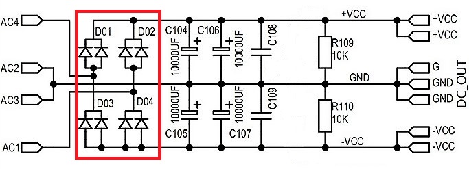
Two half-wave rectifier (Graetz bridge):
Alimentatore in corrente continua non stabilizzato con raddrizzatore a ponte di Graetz
Two half-wave rectifier (Graetz bridge) with stabilization:
Taking into account and accepting the high negative feedback that any stage of stabilization involves, whether it is made with integrated circuits or discrete components.
Alimentatore in corrente continua con uscita stabilizzata (raddrizzatore a ponte di Graetz)
Double half-wave rectifier with two diodes:
Alimentatore in corrente continua non stabilizzato con raddrizzatore a due semionde
Preferred solution to that of the trivial and cheap Graetz Bridge, because by installing one or more diodes (perhaps fast type and still much better than the normal Graetz Bridge) in parallel for each branch, you can significantly reduce the internal resistance of the entire stage of power supply, bringing our power supply to the ideal Theoretical Voltage Generator.
An aspect punctually ignored also in expensive and prestigious amplifiers and that repays with a sound clearly more seductive and realistic.
- Home
- Amplifiers
- Solid State
- NAP-140 Clone Amp Kit on eBay