Why the concern over 5% tolerance resistors?
I tought it is important to use the same resistors like the company have done it.
As i was playing around with resistor types in naim clone, found one part of the circuit were resistor type or it's tolerance matter's... i am not sure which parameter matters most...
Its feedback nest 27K and 1k, 1% metal is a better choise compared to carbon 5% or some other paralleled combination of higher resistance components.
I have heard older ppl doing this razer cut thing but never done it myself....... its a thing of the past

I will then wait for my tantalums to arrive and try them in. And then some FZT651 and FZT751... they should be adequate for voltage ratings
Try to remove the two 10uF caps and transistors based on this schematics. That would improve the sound a lot.
No, there is nowhere to improve the sound lol
... i like it as it is right now.The longer the clone is turned on under a thick carpet... the more valve like it turns ....
I even have some "forward" sounding effect left from the speakers...
Sometimes loud screaming female voices my be disqusting but thats not much of an issue i could fix with removing or adding components.
OK, you are just staying true to the original spec. Perhaps you don't realise that even with a nominal 5% tolerance, the parts you have could still all be within 1% of the value. As I mentioned, MF resistors can be trimmed to very close tolerance in normal production so it's unlikely with a 5% spec, that actual values were so widely distributed. I recall that the standard grade MF tolerance was 2%, even in 1970. Over the production life of the NAP 110/140 models, you can be sure that actual resistance distribution was narrower than 5% too.
However, I can't see that loose tolerance parts will do anything positive for you or get closer to the original product, other than to have less predictable performance and limit the value of your experiments.
However, I can't see that loose tolerance parts will do anything positive for you or get closer to the original product, other than to have less predictable performance and limit the value of your experiments.
You always have a way with words and I just can't get over how eloquent they always come across. We need more people like you Ian.OK, you are just staying true to the original spec. Perhaps you don't realise that even with a nominal 5% tolerance, the parts you have could still all be within 1% of the value. As I mentioned, MF resistors can be trimmed to very close tolerance in normal production so it's unlikely with a 5% spec, that actual values were so widely distributed. I recall that the standard grade MF tolerance was 2%, even in 1970. Over the production life of the NAP 110/140 models, you can be sure that actual resistance distribution was narrower than 5% too.
However, I can't see that loose tolerance parts will do anything positive for you or get closer to the original product, other than to have less predictable performance and limit the value of your experiments.
Yes the tighter the tolerance the more predictable and precise their values will be. For quasi complementary builds like this I am not sure how critical it needs to be but for class A builds (especially for the output devices) the resistors need to be precise. You can read more about it here,Ok, thanks Ian,
Yep, this fact point to 1% rated resistors also... must have even closer tolerance to eachother.
Output Transistor matching in powerful amps | Page 2 | Audiokarma Home Audio Stereo Discussion Forums
Thanks for your kind words. Electronics isn't really my field but I'm inspired to write as well as I can by other members and some of them are recognized authors in audio and other electronics fields - hard acts to follow. In fewer words, a good writer can give insight to baffling and subtle design issues that might have eluded us for years, as happens to me.You always have a way with words...
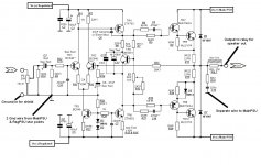
Ian do you think it worth to try the separate front power supply with regulated PS based on these schematics.
Please let me know what do you think
Is this what you have right now ? MJL21194 as outputs ?
From my experience, building complex PSU-s around H-140(basically same as NCC200) will get you no where.
Rene
Hi Gabor. No, I don't think this is the way to go with simple Lin-Thompson topology, like all NAP and early Nait series models. The front end actually interacts with the output stage via the supply rails, as Rensli just alluded to. He went through this learning experience some time back and it echos what others have said about using refinements which isolate the power supplies for the 3 stages - particularly those designs that have been tweaked in more than one stage for best harmonic profile. It will screw that up completely and leave you with the sound quality of typical text book designs from the 1970s. In one my own tests on a clone of mine, I had clean and crisp sound but it sounded disappointing by comparison - no PRT effects etc.
Hugh Dean reminded of this interaction effect when discussing his own designs up to to the NAKSA 80 stage several years ago now and I know he has a lot more experience with using the principle to best advantage than any of us here. I don't pretend to be an audiophile or designer but I can say that Naim sound depends on this effect as well as a couple of other features that seem contrary to good engineering practice.
Naim designs have probably been denounced for technical reasons ever since Julian Vereker tinkered with an original prototype to come up with the first series NAP200 and 250. Still, they sounded much better to him and his supporters, than the designs they were based on and the competition. He was self-taught and his methods had little of the restraint that would have come with formal studies in electronics but the resulting demand for products continues to speak for itself.
.Ian do you think it worth to try the separate front power supply with regulated PS based on these schematics.
Please let me know what do you think
Thank you
It is always interesting to experiment, but I am also convinced that the power supply is separate and moreover stabilized (with the inevitable negative feed-back that in dynamic operation would be inserted directly on the signal line, in the delicate stage of initial voltage preamplification ) would not bring any advantage but only heavy consequences.
.
As foreseen in the original project, the separation between the preamp stage and the power stage, thanks to the two diodes placed on the two power lines, is already an efficient and perfect solution, in order not to bring the perpeters from the power stage to the delicate one of the pre-amplification stage.
.
Member
Joined 2009
Paid Member
Member
Joined 2009
Paid Member
Hi Gabor. No, I don't think this is the way to go with simple Lin-Thompson topology, like all NAP and early Nait series models. The front end actually interacts with the output stage via the supply rails, as Rensli just alluded to.
Same goes for the AKSA amplifier and many others of similar topology.
No, there is nowhere to improve the sound lol
Gaborbela was suggesting to remove the current limiting circuit. It has contribution to safety, not sound.
As i was playing around with resistor types in naim clone, found one part of the circuit were resistor type or it's tolerance matter's... i am not sure which parameter matters most...
Its feedback nest 27K and 1k, 1% metal is a better choise compared to carbon 5% or some other paralleled combination of higher resistance components.
It's not the tolerance, but the material type/construction that affects the noise performance.
I even have some "forward" sounding effect left from the speakers...
Sometimes loud screaming female voices my be disqusting but thats not much of an issue i could fix with removing or adding components.
It is called distortion. It is the only issue with classic Naim circuits. It is difficult to get low distortion from that topology. Newer Naim circuits is better sounding to me. It removes the fatigue associated with older Naims and still bring some of the important secret sauces from the older designs.
Gaborbela was suggesting to remove the current limiting circuit. It has contribution to safety, not sound.
Actually, it does improve the sound significantly when I removed the current limiting circuit from an Ebay purchased (Jims Audio) kit.
Of course, when I found the NCC200 circuit I converted my Naim clone to that.
You will lose some of the tube-like warmish sounds in exchange better dynamic cleaner mid-bass more control more authority.
To those who want NAIM like sounds better to keep your close as close as possible to the Naim circuit.
This is a potentially stupid question: is it okay to use a 30V transformer instead of 28V?
I'm asking because 42.4V is not that far off from 39.6V, plus voltage fluctuations where I live can go between +10% and -6% of its 230V.
Also 30V transformers are more common albeit only having 2 outputs instead of 4 or 2 CT outputs.
I'm asking because 42.4V is not that far off from 39.6V, plus voltage fluctuations where I live can go between +10% and -6% of its 230V.
Also 30V transformers are more common albeit only having 2 outputs instead of 4 or 2 CT outputs.
This is a potentially stupid question: is it okay to use a 30V transformer instead of 28V?
I'm asking because 42.4V is not that far off from 39.6V
It's fine. All the original transistors can handle a bit increase in supply rail (and the associated increase in power/heat). Takes for example the ZTX753. It can handle at least 100V between Collector and Emitter.
Not Ideal. The continuous power rating of the little E-line VAS transitors is a limiting factor here and whilst Vceo is 100V, they may fail under surge conditions at much over 45V rails. You may have wondered why even the largest model, NAP 250, only has 40V power rails too and it's rated at 125W/4R but importantly, the 40V rails are regulated. You don't see this when the schematic is only a part of the design and it isn't even the right design for NAP140!
NAP140 has 34V rails, not the 40V rails shown on the NAP250 schematic you see everywhere. A 25-0 + 25-0VAC transformer is a standard value and a 160 - 200VA toroidal type is what will do fine there.
NAP140 has 34V rails, not the 40V rails shown on the NAP250 schematic you see everywhere. A 25-0 + 25-0VAC transformer is a standard value and a 160 - 200VA toroidal type is what will do fine there.
Well yes, this is different. I had to buy a 500VA transformer from China for my NAP200 clone because of the requirement for 2 sets of 28V paired windings connected as a centre-tapped winding for each power amplifier. NAP 200 is a "dual mono" design with benefits electrically close to monobloc amplifiers, so it needs this isolated supplies arrangement. It should also have 2 sets of 12V paired windings connected as centre tapped windings for a preamp, if you pair it with the appropriate NAC model or a clone.
I actually found it cheaper and with better quality windings from China but this transformer only supplies the power amplifiers. Its a heavy brute and the case needs to be strong as well as thick aluminium: Aliexpress.com : Buy GZLOZONE 500VA ( 500W ) Black Cloth Toroid Transformer For NAP200 Amp 28V 0 28V 28V 0 28V from Reliable transformer amp suppliers on Shop2656215 Store
Make sure the primary voltage is suitable for your local supply and if there is a difference, it results in lower rather than higher secondary voltages. e.g. If your local supply is 240V, don't buy a 220V rated transformer as you may as well buy a 30V transformer with correct primary windings. A 230V rated type should be OK as the unloaded secondary voltage would not typically rise more than 10% above the nominal 28VAC or 40VDC.
Transformer secondary voltages are specified at full rated load and this is quite high - 4A continuous for each centre-tapped pair of windings here. When idling with almost no current demand, the secondary voltage rises, in this example by 6% so the AC is now about 29.7V and the rectified DC about 42V. Under load, the voltage will fall again according to the spec. The effect is called the transformer's regulation and it depends on the size of the transformer, construction and winding resistance.
Voltage will dip in concert with the load, noticeable with heavy bass output but the point is that mains and mains power supply voltages are somewhat rubbery rather than fixed. Having a mains supply mismatched to the transformer adds another variable so watch what you buy and be careful with what specs mean for you, where you live.
- Home
- Amplifiers
- Solid State
- NAP-140 Clone Amp Kit on eBay