BTW, Digikey in the US are distributors of Allegro Sanken products and man, they are fast! 4 days to my location from wherever their distribution location is in S.E. Asia. My shipment of Power transistors last month was freight-free for an AU$ 50 minimum order and the offer still stands. For the total cost, that's more than competitive with other international players like the Avnet companies.
Re your schematic: post #2714I put all new tants as well.
C1 & C2 should be rated at 25V or higher and should be reversed so the negative sides are towards the transistors.

Re your schematic: post #2714
C1 & C2 should be rated at 25V or higher and should be reversed so the negative sides are towards the transistors.
Thanks, the PCB was actually marked correctly for these so these are all good.
Don't try to increase bias on a NAP or Nait design amplifier because they are a quasi complementary design which not only has lower THD at a very low bias current but will be more thermally stable there. Raise that current to where you might bias a typical complementary EF design (like every other design you see) and you'll likely soon see the temperature keep rising by itself in thermal runaway followed by smoke .
For best results and stability, the complete amplifier should be run in a compact, closed aluminium case which is also the heatsink, like the original product. They run fairly cool in an average room and are quite reliable if you get the right size case and materials.
The link below is to an interesting experiment on bias level in a Nait2 model - same circuit, lower power. It makes it pretty clear why you don't need to raise bias current, even though can, provided there is more efficient heatsinking located beneath the PCB, to support the higher dissipation whilst maintaining thermal "feedback"to the Vbe multiplier transistor. That's critically important if you raise bias level significantly.
Just one thing about music - when it hits you feel no pain
Scroll down the subject index to the "More Naim stuff" and click on the item "Bias settings in Naim amplifiers". This will open a new page and the article. There's lots of info. on Naim and other UK design products on that archive and also the parent Pink Fish Media forum, where you find commercial UK products and DIY projects discussed together, which seems to suit the active community they've built up over many years. Give at least the d.i.y. forum section an occasional read. d.i.y. | pink fish media
Thanks for the link to that article.
I was thinking that the bias needed to be closer to 30mA as per a lot of instructions on setting the bias that I've read (usually saying aim for 10-14mV across both resistors). From a distortion point of view I can see there is no need to go higher than the 20mA that I already get.
The case I have is maybe a little bigger than the contents and I have already covered up the air vents provided. Even after running the amp for a while, the case remains cool. I was wondering if the transistors are generating enough current and sinking enough heat to get warmed up.
The input and VAS stages draw about 10mA. At idle, the drivers should draw about 7mA. So if the supplies draw 20mA total then you would expect the output transistors are drawing only 3mA or so.
The voltage between the driver bases should be in the region of 2.8V. If it is higher than this there is a fault in the output stage. Is the diode open-circuit?
I've got about 1.5v between the bases.
I took some measurements and I'm not sure everything is ok even though I am getting getting music out. Both LH and RH board measurements are comparable.
Measurements with 40v rails, no input or output connected, amp run for a period of time enclosed but didn't really warm up. Bulb limiter bright then dims as normal, removed for measurements.
Output transistors (2SC2922) I get:
C:E = 40V
C:B = 40V
B:E = 600mV
C:E = 40v
C:B = 40v
B:E = 582mV
Drivers:
C:E = 40v
No significant voltage between TR4(C) : TR7(B)
Significant voltage (38.5v) between TR6(B) : TR8(B)
Bias generator voltage TR4(C) : TR6 (C) = 1.18-1.63v (Range with trimpot)
DC offset is around 7mV.
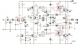
I've attached an annotated schematic.
Attachments
Hi,
A little unusual selection of test points ... but they give some idea.
The circuit looks OK. 1.53V is just what it should be.
Now, you've rounded too much the 40V measurements and it's hard to tell what are the currents. I have suspicion that the input pair may have slightly low current. Can you measure across the 620 and 68 ohm resistors on the bottom of the schematic. That will give info for the currents in the LTP and the VAS stages.
In general, ground is the most stable reference. It's much easier to fix the black probe of the DMM to it, and then just walk around the test points with the red one.
A little unusual selection of test points
... but they give some idea.The circuit looks OK. 1.53V is just what it should be.
Now, you've rounded too much the 40V measurements and it's hard to tell what are the currents. I have suspicion that the input pair may have slightly low current. Can you measure across the 620 and 68 ohm resistors on the bottom of the schematic. That will give info for the currents in the LTP and the VAS stages.
In general, ground is the most stable reference. It's much easier to fix the black probe of the DMM to it, and then just walk around the test points with the red one.
Last edited:
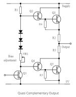
That's the point I was making, this is not like a lot of other amplifiers which have symmetrical, complementary output stages. It's time to hit the books*. Referring to the simplified diagram, look at the different arrangement of the driver transistors where they connect to the upper and lower output transistor bases. Maybe you wondered why the output transistors in the kit were all the same? Well, this is a very 'old-school' quasi-complementary design where one base is driven from a driver collector and the other from its driver emitter, thus getting a phase inversion that is necessary to use same-sex output transistors, as once was necessary. Hence it's called quasi-complementary......I was thinking that the bias needed to be closer to 30mA as per a lot of instructions on setting the bias that I've read....
This also means there is a different bias voltage, hence bias current required to bring either half to conduction as they switch on and off at crossover. It's the lower (Szlikai) half that switches first and dominates the crossover behaviour, as the article shows. There is no other purpose for bias current than to optimise crossover linearity so that's what we focus on.
The optimal bias currents for a complementary emitter follower (EF) design are indeed around 30mA, depending on the emitter resistor value used. A complementary CFP or Szlikai output stage has only one junction to forward bias and a lot less current is needed to forward bias it, so 12-15mA current is plenty. The quasi form is a compromise of one and two forward junctions to bias with the same current but as said, the CFP form dominates actual performance.
Follow the advice specific to the design. 7mV measured across one of the appropriate 0R22 resistors is spot-on and there is no need to tinker - but as you find, it takes forever to warm up a big case with that trickle of current in order to set that voltage properly. BTW, is that a thick, say 3-4mm aluminium case? If it's thin or steel material, you may find the point of attachment is the only hot spot and that heat is not being conducted away effectively. A finger on the top of the power transistors will soon tell you. Google some pics of NAP models and you'll see that all have heat spreader bars or hollow section aluminium extrusions to spread the heat more evenly to the case, increasing cooling for the full rating of the various models. Since all NAP models used virtually the same parts, that leaves only the case and the power supply as the main difference between them. Not a bad way to squeeze more profit from a small parts inventory
I've had a few Naim models to test and service over many years and they are all slow to warm up because the bias required is only small. Some that had the PCB mounted up near the top of the case were faster to warm up via convection - others like NAP200 have the Vbe multiplier transistor mounted on the under side of the PCB with the PCB close to the bottom for an even faster response..... I have already covered up the air vents provided. Even after running the amp for a while, the case remains cool. I was wondering if the transistors are generating enough current and sinking enough heat to get warmed up.
The heat dissipation at full continuous power may be significant but domestic music levels generate nowhere near that amount so the amplifier won't run hot unless like me, you don't have air-con and in 40C weather, everything becomes hot to touch. Nevertheless, you could set the bias using the same loading method to warm up the amplifier as described in the article. You may not be familiar with test and measurement procedures but when you build electronic devices, the old discrete designs don't simply fall together without some technical information, instruments and ingenuity. It's worth thinking about, if you like to build power amplifiers.
* If you don't like wading through technical details, Douglas Self's books do take you through the topics more easily than most. On his website, you'll find various basic design types in his approach to nailing distortion. Go to the output stage distortion comments here:
Distortion In Power Amplifiers - Home Warranty Appliances
This is specific to quasi-comp. designs: Quasi Complementary Transistor Output | Radio-Electronics.Com
Attachments
Hi,
A little unusual selection of test points
The circuit looks OK. 1.53V is just what it should be.
Now, you've rounded too much the 40V measurements and it's hard to tell what are the currents. I have suspicion that the input pair may have slightly low current. Can you measure across the 620 and 68 ohm resistors on the bottom of the schematic. That will give info for the currents in the LTP and the VAS stages.
In general, ground is the most stable reference. It's much easier to fix the black probe of the DMM to it, and then just walk around the test points with the red one.
Thanks Ruwe
I went through the test points that Bigun wrote a couple of pages ago.
I've since measured all of the transistor B:E to make sure they are at their turn on voltage. All were dropping around 600mV, so all good there. (Except the outputs were dropping about 150mV).
I had a good look at the board versus the schematic and decided to change the VAS resistors to reflect the schematic. I felt that this was the limiting factor for the biasing voltage.
The PCB had:
1k pot instead of 2k2
1k5 instead of 2k7 between collector ZTX753 and TR5
2k2 instead of 1k2 at the trimpot
Once running, I got free movement of the bias as far as runaway so I am happy that the board is behaving more as it should.
I set the current to a nice stable 25mA while warm (and the output transistors are now actually warmimg up). I could also see the thermal coupling effect by touching the ZTX 753 and 653 - the bias would drop a mA or two then recover as it heated back up again.
But as always, the proof of the pudding was in the listening.. It sounded clearly better than before - I didn't need to turn the dial too far and the sound was much clearer than before.
Next step, get some genuine output transistors and see if it can sound any better!
Thanks Ian, for taking the time to write a detailed response.
I get that these are quasi-complementary - My intent with the bias was not about pushing boundaries or trying to disprove any of the wisdom/opinions regarding bias - it was merely that the board was not behaving as many people over many threads have described.
In multiple posts and guides that I've read through, the target bias voltage was said to be 14mV across the two 0.22r output resistors for these boards.
At full deflection of the VR, either side I was only getting 1mV to 2mV and when connected through an ammeter, I was getting 20mA at full deflection of the VR. This told me that something was probably not right with the way the boards were set up (as both PCBs were behaving the same).
I'm too new to this particular avenue of electronics to have an opinion on bias so I needed to blindly set up the bias to the voltages (amperages) that are stated on the schematics, the multiple posts and the guides. Being able to now see mV readings across those resistors that are comparable to the schematics and other's reports, makes me feel like the boards are behaving closer to how they should and gives me a good starting point.
The case is thick aluminium. The output transistors are mounted on the underside of the boards and bolted to the case with thermal compound and thin insulation pads.
Haha I'm in the city of churches with no aircon and 40c+ weather too!
That is the reason I have taken up this challenge. I have a decent grounding in another electronics/electrics field but power amp design is something I've been interesting in trying to comprehend for a long time. I'm already wading through Douglas Self's power amp design book and I know that I know nothing! But we have to start somewhere.
That's the point I was making, this is not like a lot of other amplifiers which have symmetrical, complementary output stages. It's time to hit the books*. Referring to the simplified diagram, look at the different arrangement of the driver transistors where they connect to the upper and lower output transistor bases. Maybe you wondered why the output transistors in the kit were all the same? Well, this is a very 'old-school' quasi-complementary design where one base is driven from a driver collector and the other from its driver emitter, thus getting a phase inversion that is necessary to use same-sex output transistors, as once was necessary. Hence it's called quasi-complementary.
I get that these are quasi-complementary - My intent with the bias was not about pushing boundaries or trying to disprove any of the wisdom/opinions regarding bias - it was merely that the board was not behaving as many people over many threads have described.
In multiple posts and guides that I've read through, the target bias voltage was said to be 14mV across the two 0.22r output resistors for these boards.
That voltage should be initially set to no more than 7+7 mV or 14mV and this means approx. 32 mA bias current.
At full deflection of the VR, either side I was only getting 1mV to 2mV and when connected through an ammeter, I was getting 20mA at full deflection of the VR. This told me that something was probably not right with the way the boards were set up (as both PCBs were behaving the same).
I'm too new to this particular avenue of electronics to have an opinion on bias so I needed to blindly set up the bias to the voltages (amperages) that are stated on the schematics, the multiple posts and the guides. Being able to now see mV readings across those resistors that are comparable to the schematics and other's reports, makes me feel like the boards are behaving closer to how they should and gives me a good starting point.
Follow the advice specific to the design. 7mV measured across one of the appropriate 0R22 resistors is spot-on and there is no need to tinker - but as you find, it takes forever to warm up a big case with that trickle of current in order to set that voltage properly. BTW, is that a thick, say 3-4mm aluminium case? If it's thin or steel material, you may find the point of attachment is the only hot spot and that heat is not being conducted away effectively. A finger on the top of the power transistors will soon tell you.
The case is thick aluminium. The output transistors are mounted on the underside of the boards and bolted to the case with thermal compound and thin insulation pads.
The heat dissipation at full continuous power may be significant but domestic music levels generate nowhere near that amount so the amplifier won't run hot unless like me, you don't have air-con and in 40C weather, everything becomes hot to touch.
Haha I'm in the city of churches with no aircon and 40c+ weather too!
Nevertheless, you could set the bias using the same loading method to warm up the amplifier as described in the article. You may not be familiar with test and measurement procedures but when you build electronic devices, the old discrete designs don't simply fall together without some technical information, instruments and ingenuity. It's worth thinking about, if you like to build power amplifiers.
That is the reason I have taken up this challenge. I have a decent grounding in another electronics/electrics field but power amp design is something I've been interesting in trying to comprehend for a long time. I'm already wading through Douglas Self's power amp design book and I know that I know nothing! But we have to start somewhere.
Good reply.
Perhaps I can repeat some background that may be useful to newcomers with a plan to get their clone going as a reasonable clone rather than a so-so generic amplifier.
The usual schematic that was posted is deceptive because it is untitled, has higher marked rail voltages and seems closest to a NAP 250, a much larger, more powerful beast which required regulated power supplies and substantial heat spreading for both regulators and power amplifiers. The transformer was consequently huge but regulation is a must when the same basic design is pushed to the max. to drive large speakers for the sort of home this model was priced for. With regulated +/- 40V supplies as shown, NAP250 delivers a genuine 125W/4R from a single pair of transistors and sounds great. High-end of the 1980s, you might say.
Many will assume that you can use an unregulated supply with the nearest stock toroidal transformer, probably a 230 or 115V:30+30VAC type, giving loaded rail voltages of +/- 43VDC but unloaded supplies could then climb to +/-46V. This isn't a problem for the modern semis now used in the output stage but it is for their heat dissipation and the critical small-signal transistors in the front end which are already stretched. This needs to be dealt with if you expect to get comparable sound quality and performance. A stock 24+24 or 25+25VAC transformer would better suit a real NAP140 clone.
In the fine detail, that schematic is like nothing we've seen from Naim. The circuit is OK but some critical parts and values seem to be generalised, perhaps intended for service people to follow the operation of several or all models. Unfortunately, it's all we have that's official. In other words, following that NAP250 schematic with the typical components supplied in the cheapest kits, does not result in audio nirvana, that much I can vouch for. Some kits actually do contain good parts equivalents, genuine semis and perfect copy PCBs. The expensive Caowei NAP200 kit, for example, makes up to a really worthwhile clone that is convincing and satisfies me at least. A similar, cheaper kit was not so good, as there were fake, perhaps re-labelled semis and poor substitute type caps in the example I saw.
Otherwise, following the NCC200 schematic (the bright yellow/green one you find) is a more reliable way to get good quality sound because it's easy to duplicate and follow the few instructions with currently available components but it doesn't deliver the same sound quality as Naim gear and some will dislike it whilst others prefer it for that reason.
Hi again guys,
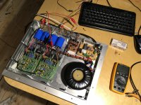
As you can see, i have finished full naim as close i could to the original.
In short:
My transformer voltage is rectified: 2x35V DC @ 238V AC mains, Power rating: 300VA
Cuz of that overkill Xformer VA rating i wanted to ADD DC protect for speakers, just in case... VI LIMITER is not enaugh if 2SC2922 shorts ;D out
I couldn't do it with relays, not either with MOSFET(tried LOW RDSON type and IRF540 type.
Both methods RUINED the sound quality... The Sound is softer and liquid without the PROTECTIONS..
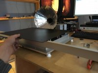
On LAST two photos protection are removed.
I am listening to it, its very very musicial lol...whats wrong with ppl who mod this stuff ???
MY PSU ARRAGEMENT is 1:1 with naim !! Bridge rectifiers are almost the same type(604 series).
The only drawback is the capacitor bank... i dont have high quality 4700uf barrels... so i used:
10000uf 40V barrels...
Also, the NAIM amplifier and i belive all of them does not sound in free air...
The circuits idea is to get warm and stay warm for pleasing sound!
Rene
As you can see, i have finished full naim as close i could to the original.
In short:
My transformer voltage is rectified: 2x35V DC @ 238V AC mains, Power rating: 300VA
Cuz of that overkill Xformer VA rating i wanted to ADD DC protect for speakers, just in case... VI LIMITER is not enaugh if 2SC2922 shorts ;D out
I couldn't do it with relays, not either with MOSFET(tried LOW RDSON type and IRF540 type.
Both methods RUINED the sound quality... The Sound is softer and liquid without the PROTECTIONS..
On LAST two photos protection are removed.
I am listening to it, its very very musicial lol...whats wrong with ppl who mod this stuff ???
MY PSU ARRAGEMENT is 1:1 with naim !! Bridge rectifiers are almost the same type(604 series).
The only drawback is the capacitor bank... i dont have high quality 4700uf barrels... so i used:
10000uf 40V barrels...
Also, the NAIM amplifier and i belive all of them does not sound in free air...
The circuits idea is to get warm and stay warm for pleasing sound!
Rene
Attachments
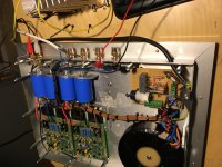
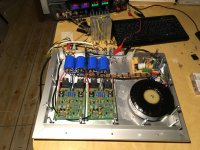

That new build of yours looks very good with those ZeroZone PCBs and your classy tying of the power supply leads 
That's also an interesting way to build the enclosure. Is there a wide gap between cover and case? I would consider closing any gaps to ensure Bias tracks with output stage temperature as well as possible, if so.
That's also an interesting way to build the enclosure. Is there a wide gap between cover and case? I would consider closing any gaps to ensure Bias tracks with output stage temperature as well as possible, if so.
Thanks guys
There will be no air gaps.
On the photo you see Black metal plate ordered from toroidy.pl and a L-aluminum profile anodized.
PLYWOOD will be used instead of black metal cover, to keep amplifier warm...
The buttom plate is very thick and enaugh for everything
Guys, i used 1mm2 copper nickel plated wire everywhere.. the wire coating is rated at 105C !!
The only protection is the original VI limiter
Filters used:
33R & 27R into MJE 243 base
560 % 390 into MJE 253 base
All original 2SC2922 (44P) are 111+ HFE when measured with chinese transistor tester @ 20C ambient.
The 2sc2922 (81 Y) that came with the kit are too low HFE (33+) and they'r weight less then the originals, i let them be and did not used them..
15g vs 18.33g
The amp drives beta 10 cx bass reflex type.
Next build will be NCC200 with 200VA 39V DC transformer.
Attachments
The 2sc2922 (81 Y) that came with the kit are too low HFE (33+) and they'r weight less then the originals, i let them be and did not used them..
15g vs 18.33g
The amp drives beta 10 cx bass reflex type.
Next build will be NCC200 with 200VA 39V DC transformer.
Hi
Yes, those transistors are fake, I have some. I built the DoGC amplifier and when I powered up the transistor literally exploded into my face.
I do like your metal work! It will be nice, Are you planning to add some face plate (wood or something for decoration)
I do like the NCC200, I built the original Naim Clone and the NCC200 to me the NCC sounded way better, much cleaner mids, precise, and better bass with better dynamics. Your transformer will be enough for one channel. I may work because of the low bias of the amplifier but will suffer when you crank it up. If you read the transformer recommendation at the Avondale site you will see what I talking about. If you plan to purchase a transformer please buy a 300VA, if you already have one try to get one more and build a dual mono set up.
I like your amp looks a lot!


gaborbela
Hi, i have owned many types of NCC200, its impossible to listen to piano or ambient music with NCC200 type amplifier... i think i had always done something wrong working around that circuit... but it never was so musical as naim..
Naim is like wanna be valve, but faster ... funny to listen lol....
It has its drawbacks... for example... if someone shout's... it could be disgusting with naim amplifier....
NCC200
my nap 140
Nice build !!!
Where did you get those polystyrene miller and feedback RC capacitors ?
And that blue tantalum... i wonder whats its ESR ?
Output transistors, type ? Capacitor bank voltage rating and capacity ?
Wire gauge ?
Last edited:
- Home
- Amplifiers
- Solid State
- NAP-140 Clone Amp Kit on eBay