In reference to Ebay clones, those resistor values would only be supplied or specified with recent kits from just Caowei and ZeroZone so far, I think. Their clones of NAP200 and 140 do seem to follow the original designs faithfully but up until last year, all NAP 140 clones followed the common NAP 250 design, as they have for ten years or more now.There are countless photos about these resistor values, al seems legitable and original.
This is fine if you have the correct schematic to go with these newer boards but I don't think that's going to happen. The sellers say in their offers "sorry no schematic or instructions - parts placement is shown on the PCB". If you just buy the boards, you may have to draw up your own BOM from the overlay and over-write a 250 schematic with the parts shown. Seems a good reason for buying the kits rather than just PCBs.
In reference to Ebay clones, those resistor values would only be supplied or specified with recent kits from just Caowei and ZeroZone so far, I think. Their clones of NAP200 and 140 do seem to follow the original designs faithfully but up until last year, all NAP 140 clones followed the common NAP 250 design, as they have for ten years or more now.
This is fine if you have the correct schematic to go with these newer boards but I don't think that's going to happen. The sellers say in their offers "sorry no schematic or instructions - parts placement is shown on the PCB". If you just buy the boards, you may have to draw up your own BOM from the overlay and over-write a 250 schematic with the parts shown. Seems a good reason for buying the kits rather than just PCBs.
With regards to the NAP 200 BOM, Algar_emi had posted one some time last February 2016
http://www.diyaudio.com/forums/solid-state/112453-nap-140-clone-amp-kit-ebay-218.html#post4609140
I've added that BOM in this post as well.
But yes I do agree buying the whole kit with the components supplied will be easiest. They do match the components well.
This whole confusion is because the NAP 140, 200, 250 all are in this one thread. Their schematics do look very similar. I would open a separate thread myself but my extent of DIY skills is just parroting what the guides online show. Probably not the best man for the job.
The amp sounds very good though. I have a hard time justifying any upgrades. I accidentally left the NAP200 on for a week plus because I wasn't staying at home and it only felt warm to the touch. No boom, no fire = good for me.
Only need to change the internal wiring. Currently using very rigid thinly insulated magnet wires. To be honest when I bought it I thought it was a standard teflon insulated copper wire. Im going to use cables intended for making headphone cables, combination of copper and silver.
Attachments
Last edited:
Assuming you are talking about the few transformer power and output leads, you need to make sure that the total cross-sectional area of the wire is as large enough for the current. Solid magnet wire may be rigid and awkward to route inside the box but at least will stay in position and handle the current well without power loss. AFAIK, most headphone wire is very light gauge, though I have no idea how crazy over-powered some headphones and accessories may have become in recent years.Only need to change the internal wiring. Currently using very rigid thinly insulated magnet wires. To be honest when I bought it I thought it was a standard teflon insulated copper wire. Im going to use cables intended for making headphone cables, combination of copper and silver.
BTW, though generally similar to all NAPs, the NAP 200 has different and improved VI current limiters to earlier designs - long overdue.
Assuming you are talking about the few transformer power and output leads, you need to make sure that the total cross-sectional area of the wire is as large enough for the current. Solid magnet wire may be rigid and awkward to route inside the box but at least will stay in position and handle the current well without power loss. AFAIK, most headphone wire is very light gauge, though I have no idea how crazy over-powered some headphones and accessories may have become in recent years.
BTW, though generally similar to all NAPs, the NAP 200 has different and improved VI current limiters to earlier designs - long overdue.
I agree with your concern about the output and power leads, but I was referring to the input leads from the RCA. The transformer leads had been cut to length, has no hum so no need braiding or twisting and they look very neat right now, while the speaker output leads I will either probably leave them as they are now, or replace the magnet wires with power cable wires which is what I use for speaker cables. The only advantage when it comes to the power wires for speaker outs are they're a lot more flexible. I doubt there will be any gains when it comes to sound.
This is the cable I'm planning to get for the RCA inputs. There are 3 material variations with 2 braid variation each. I am getting the silver+copper round braid instead of flat braid.
https://www.aliexpress.com/item/Headphone-Wire/32767554889.html
There are overpowered headphones, especially electrostats with hundreds of volts running through them, some 600 ohm headphones that requires high power, etc but none need wires as big as speaker wires.
Really, plain shielded wire is what you need for RCA input sockets. For the short distance to the rear panel in an area unexposed to noise, a twisted pair of plain, light duty hook-up wire would be excellent too. I don't think those exotic speaker cables you are planning on are going to be much fun to strip and solder together, frankly - all for just a few inches of connecting lead  .
.
.Hi!
My electrical schematic is:
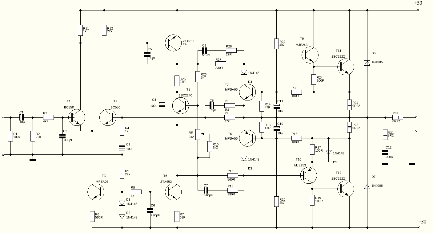
I use regulator for power supply (30V).
I tested some pair R27/R28 and R16/R15
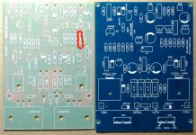
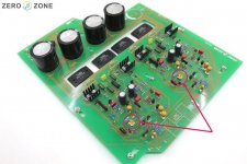
1. Green original PCB - R27/R28:33Omh/27Omh R16/R15:390Omh/560Omh. Sound is metallic. Error on PCB - R27 should be 330Omh
2. Blue PCB - R27/R28:680Omh/560Omh R16/R15:390Omh/560Omh. Sound is a lot bass frequencies and small
treble
frequencies
3. R27/R28:330Omh/27Omh R16/R15:680Omh/27Omh. Sound is "bright" and "light"
4. Green PCB without error - R27/R28:330Omh/27Omh R16/R15:390Omh/560Omh. Sound is good. Bass and treble is ok. Not "bright" or "light" sound.
My electrical schematic is:
I use regulator for power supply (30V).
I tested some pair R27/R28 and R16/R15
1. Green original PCB - R27/R28:33Omh/27Omh R16/R15:390Omh/560Omh. Sound is metallic. Error on PCB - R27 should be 330Omh
2. Blue PCB - R27/R28:680Omh/560Omh R16/R15:390Omh/560Omh. Sound is a lot bass frequencies and small
treble
frequencies
3. R27/R28:330Omh/27Omh R16/R15:680Omh/27Omh. Sound is "bright" and "light"
4. Green PCB without error - R27/R28:330Omh/27Omh R16/R15:390Omh/560Omh. Sound is good. Bass and treble is ok. Not "bright" or "light" sound.
Attachments
Last edited:
Nap140 clone vs symasym
Dear Andrew,
Please advise which better Nap140 clone vs Symasym5.3 ?
Thanks,
Fariz
(Sundanese)
Reverse voltage of <5%*50V rating gives a maximum 2.5Vreverse,
going down to <1%*12V giving a maximum of 0.12Vreverse.
Thanks for that Vishay info
Dear Andrew,
Please advise which better Nap140 clone vs Symasym5.3 ?
Thanks,
Fariz
(Sundanese)
Alex74
I am not the only guy who likes Quasi Complementary output stage perfomance. It just sounds better then any other topology.... its just that.
We need to build up some reference (distortion, harmonic, impedance, stability whatever else is better) to understand exactly why FILTER NETWORKS are used on driver Base's and why Tantalums (10-68uF low or high ESR) in FB and VBE changes the sound dramatically.
Some real-time analysis is missing from this thread...
Interesting work Alex74.Hi!.....I use regulator for power supply (30V).
I tested some pair R27/R28 and R16/R15
1. Green original PCB - R27/R28:33Omh/27Omh R16/R15:390Omh/560Omh. Sound is metallic. Error on PCB - R27 should be 330Omh
2. Blue PCB - R27/R28:680Omh/560Omh R16/R15:390Omh/560Omh. Sound is a lot bass frequencies and small
treble
frequencies
3. R27/R28:330Omh/27Omh R16/R15:680Omh/27Omh. Sound is "bright" and "light"
4. Green PCB without error - R27/R28:330Omh/27Omh R16/R15:390Omh/560Omh. Sound is good. Bass and treble is ok. Not "bright" or "light" sound.
Note that the supply voltage is important to the sound quality and your results may be a little different to the original products and other builders results, according to the actual design followed in these clone kits.
The blue board follows the NAP250 generic design that is shown widely and is designed for +/-40V supply rails and various older semis that were used before 1980, I believe. The green board is correct for the actual NAP140 design which uses 34V rails and components available in much later issues of the 140 model. You won't see it anywhere else, as far as I have looked. Assuming the components supplied are genuine, the sound quality should be similar to the original, even if the supply voltage is 12% low. However, there is a question over the capacitors fitted for the phase correction filters. The originals are always polystyrene types - not sure what types are fitted to the Zerozone clones. Are they axial leaded MLCC?

1. C1 -KEMET RADIAL TANTALUM CAPACITOR 10uF 20v 5%
2. C11,C12 - 10uF 16V Tantalum Capacitors AVX Radial 2.5mm
3. C3,C4 - Tantal 100µF 100uF 10V 20% RM5 Thomson/AVX
4. C8,C7 - 510 pf green WIMA FKP2 and I tested PHILIPS KP 470pF 250V 2% Audio Polypropylene Film/Foil Capacitor. - not sound difference
5. C8,C5 - Cornell Dubilier-CDE 39P (39PF) 500V 10% Dipped Silvered Mica Capacitor
6. C2,C6 - PHILIPS Audio Polypropylene Film/Foil Capacitor
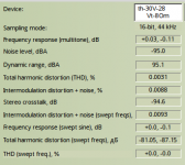
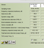
I'll post the results of tests in RMAA (distortion, harmonic, etc.....) later. It's very very good.
2. C11,C12 - 10uF 16V Tantalum Capacitors AVX Radial 2.5mm
3. C3,C4 - Tantal 100µF 100uF 10V 20% RM5 Thomson/AVX
4. C8,C7 - 510 pf green WIMA FKP2 and I tested PHILIPS KP 470pF 250V 2% Audio Polypropylene Film/Foil Capacitor. - not sound difference
5. C8,C5 - Cornell Dubilier-CDE 39P (39PF) 500V 10% Dipped Silvered Mica Capacitor
6. C2,C6 - PHILIPS Audio Polypropylene Film/Foil Capacitor
I'll post the results of tests in RMAA (distortion, harmonic, etc.....) later. It's very very good.
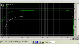
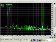
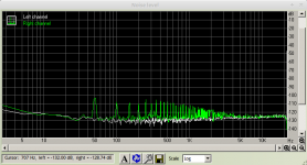
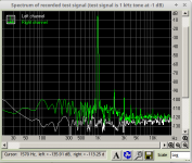
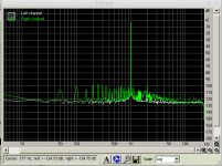
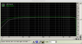
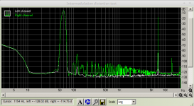
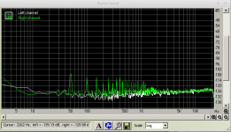
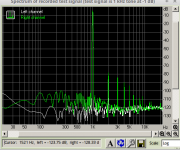
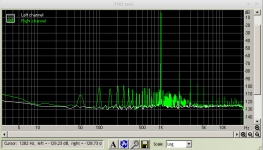
The results of tests in RMAA of my Naim 250 clone.
Only one channel test (green line - Rigth). White line is the soundcard (EMU 0204) loopback.
1. 8 Omh, Pmax=28 Вт Prms=20 Вт
Only one channel test (green line - Rigth). White line is the soundcard (EMU 0204) loopback.
1. 8 Omh, Pmax=28 Вт Prms=20 Вт
Attachments
I could not find polystyrene 39PF.Use polystyrene rather than silvered mica.
I could not find polystyrene 39PF.
LCR polystyrene:
https://www.chipdip.ru/product/fsc-160v-33pf-1pf
https://www.chipdip.ru/product/fsc-160v-47pf-2.5
Another film WIMA PP polypropylene FKP2 https://www.chipdip.ru/product/fkp2o100331d00jssd
LCR polystyrene:
https://www.chipdip.ru/product/fsc-160v-33pf-1pf
https://www.chipdip.ru/product/fsc-160v-47pf-2.5
Another film WIMA PP polypropylene FKP2 https://www.chipdip.ru/product/fkp2o100331d00jssd
Dmitry, I have a pathological allergy to this store ("Chip and Dale"), after I got four or five resistors there 3296w, and looking at the cash register - my eyes became square. Результаты поиска «3296w»
Результаты поиска «3296w» Dmitry
I found them at ebay: STYROFLEX CAPACITOR 39pF 50v NOS 4PC. C566CU93CA19U44F050615 | eBay
I found them at ebay: STYROFLEX CAPACITOR 39pF 50v NOS 4PC. C566CU93CA19U44F050615 | eBay
Naim amps do run relatively cool because they are a quasi-complementary design and operate with only about 30 mA bias current in the output stage.
The bias setting procedure has been detailed a few times in this thread. You probably don't have any schematic to refer to, so you need to identify the output transistors TR11 and 12 and the large "emitter" resistors, R11 and R12. Don't confuse them with the similar output resistor, R14. Measure the DC voltage across either R12 or R13. It will be very small and should be set to 7mV. If your meter is crap at lowest range measurements, measure across both resistors in series and adjust for twice the voltage at 14mV, which will be more precise.
Make any adjustments promptly after the amplifier has been closed and fully warmed up. If you are running the amplifier open, it will probably never warm up and stabilise, so don't try to set it without its case - you'll be wasting your time. Build your amp like the original, where the amplifier does eventually warm up warm after about 20 mins because the aluminium case is the heatsink.
I don't know whose clone you have there and what, if any, part numbering is used. The reference numbers I've used here follow the attached schematic. Yours may have nothing, so you may have to deduce the part identities from the circuit and layout, which will likely be similar to the original anyway.
Also check out some more Naim set-up, history and other details on this site archive: Modifying Naim Audio power amplifiers
Sorry for quoting a post that's almost one year old. I don't know why I didn't ask this earlier: how do I adjust the DC voltage across either R12 or R13? Using the small trimmer pots?
Attachments
Last edited:
- Home
- Amplifiers
- Solid State
- NAP-140 Clone Amp Kit on eBay