added a current source in place of the output bootstrap. played with the current settings a bit, and got the distortion down to about -55db. not sure exactly how realistic the currents are for the devices chosen. the current source is set at 14mA, and the distortion goes down a bit more if it's set to 35mA (a 20 ohm emitter resistor in the CS). so at least for the current source and VAS, the currents are reasonable for the devices chosen. the quiescent current of the output devices is a bit high at 280mA. even the devices i used as outputs (TIP31/32 because i didn't have the devices in the .asc file) would be running a bit too warm. for a lot of the mid 70's to late 80's a lot of the cheap stereos that used such amplifiers DID use the TIP31/32 as output devices anyway. the current source is a big improvement, and the use of a current source negates the need for the feedback from the speaker to linearize the VAS, so the output bootstrap goes away. now there is no current idling through the speaker.
the amp only goes to 1.5W before it clips at the PS voltage shown.
the amp only goes to 1.5W before it clips at the PS voltage shown.
Attachments
Last edited:
You are very much in error, wahab.
i did build 3 stereo amps for comparisons...
this kind of cfb , a simple differential and
a symetrical differential...
i retained the latter, which i later "upgraded"
with hitachi s sj48/sk133...
you will notice that the 2 latter amps i named are generic extensions
of this cfb topology...
wahab,
you have lost your way.
lumba, affirmation without arguments is pure rethoric..
<snip>
the amp only goes to 1.5W before it clips at the PS voltage shown.
Yeah I noticed the same thing, I chose the low voltage because the original design clearly wasn't intended for very high voltage operation or output power, although without seeing the original design documentation it is hard to know the intent.
It also does not appear to be a trivial issue to fix, although I was able to achieve some improvement. There are a combination of issues including the loading imposed by the output devices, but fundamentally this VAS design (and the variations I tried) is inefficient in terms of the required supply voltages. I made some changes that appear to increase the available swing slightly, but at some expense in linearity.
Last edited:
wahab,
rhetorically speaking, no affirmation of fact. That falls outside the scope of this discussion. Now it's all in your hands.
lumba, fact is that i tested this topology comparatively
to concurrent ones...what are the results of your
investigations on the matter?..
Kevin,
I would omit R7, reduce the value of R8, R6, R3 and insert a series gate resistor. I`d also try to omit C1.
Hi Lumba,
R7, and R8 set the supply mid point at the output of the amplifier, for your proposal to work you would have to use a bipolar power supply. Also C1 sets the closed loop DC gain to unity - it is critical to establishing the dc conditions on the output stage. (You don't want dc voltage gain in an audio power amplifier IMHO) Note that the fet operating bias is developed by R3 in addition to its function as part of the feedback network. Operating you will notice that the ~half mA of fet source current through R3 results in the source being ~2V positive relative to the gate. (Vgs is effectively -2V)
The JFET operating point is affected by the value of R3 (sets drain current with caveats) R7/R8 which establish the half supply reference and to some extent the values of R1/R2. There are a lot of very complex interactions in this design, and I have not yet figured it entirely out.
I will say I have experimented with 5 transistor designs that were very similar to this one, but with a bi-polar front end and was able to achieve both good sound and plenty of power.
Standard differential front ends are a lot easier to work with than this one is proving to be.
Last edited:
wahab,
stick to single-ended stages as far as you can.
lumba, i thought you were a more serious guy...
these SE are a total failure..it s not hifi..
what is the point of having a h2 at -40db ?..
the amp described in this hread, though it would need a few
more components, would be infinitly superior to those one legged
jurassic amps..
kevin,
Right, of course. Bipolar power supply and strenuously chosen resistor values would be necessary to do those changes. The output capacitor would still be needed due to lack of balancing mechanism.R7, and R8 set the supply mid point at the output of the amplifier, for your proposal to work you would have to use a bipolar power supply. Also C1 sets the closed loop DC gain to unity - it is critical to establishing the dc conditions on the output stage. Note that the fet operating bias is developed by R3 in addition to its function as part of the feedback network. Operating you will notice that the ~half mA of fet source current results in the source being ~2V negative relative to the gate. The JFET operating point is actually set by the feedback components R7/R8 and a bunch of other things that interact.
wahab,
evidently, you've been completely brainwashed by doctrines taken directly from marketing brochures. It is advisable to start learning about tonality before making turbid statements. Look, I have no interest in persuading you. At this point, I say you better keep believing in stupid simulations.
evidently, you've been completely brainwashed by doctrines taken directly from marketing brochures. It is advisable to start learning about tonality before making turbid statements. Look, I have no interest in persuading you. At this point, I say you better keep believing in stupid simulations.
yes, lumba, i was thinking the same...
one must be seriously brainless to "think" that a SE
solid state with vast amount of distorsion is better
than a classic amp using NGFB......
once a famed engineer propose a mediocre such
design, and everyone cries genius , while the
beast is in fact pityfull, with vast amounts of distorsion.
if that was you or me that did propose this circuit,
we would have been branded idiots, and first day beginners
amateurs...
before we all start launching nukes at each other, take a step back.... this topology is interesting, for 2 reasons. 1) it was one of the first (internally at least) DC coupled designs. up to that point, most transistor amps were solid state copies of tube amps, using transformer coupling, usually at the input stage, driver stage, and output stage. 2) it was the first complementary output stage design that could be coupled (almost) directly to the speaker. this circuit was the basis for classic SS amps like the Dynaco, which actually sounded quite good (although the SE input stage had poor PSRR).
i actually had a bit of fun with this over this weekend. adding a current source to the VAS is a large improvement, but the output bias has to be run a bit hot, almost a class "A-AB". i tried using a schottky diode as one of the diodes in the bias stack, to lower the bias a bit, the distortion went up about 10db. i'll play around with it a bit more this week, and see what i come up with. i have a few transistors laying around to make a working model too...
i actually had a bit of fun with this over this weekend. adding a current source to the VAS is a large improvement, but the output bias has to be run a bit hot, almost a class "A-AB". i tried using a schottky diode as one of the diodes in the bias stack, to lower the bias a bit, the distortion went up about 10db. i'll play around with it a bit more this week, and see what i come up with. i have a few transistors laying around to make a working model too...
. this circuit was the basis for classic SS amps like the Dynaco,
...
quiete the contrary,it s an impovement of the dynaco..
the circuit from TI is for a 12V ps, and as, it has
low output current capability, which is the main flaw
of this particular implementation...
since the output stage has no enough urrent gain,
the preceding vas is too heavily loaded...
usig a pair of emitter follower fo output stage
improve the thing a lot...
other thing is that the input fet must have a high
transconductance, and that s another flaw in this circuit,
as a bjt would provide much better global caracteristics.
using a better fet is mandatory if yo want to keep that
kind of device.
Gentlemen,
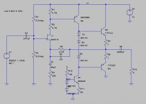
This circuit was published in the "FET Cookbook" (Das FET Kochbuch) written by the Texas Instruments application guys, back in the seventies (as far as I know it was not published in English). The question I have is not about the audio qualities of the design but the function of the 4.7 KOhm resistor connected between the drain of the FET (T1) and the base of the BC212 driver (I marked it as R2).
Apart from the possibility of eliminating a large surplus of 4.7 K resistors in the lab, I really honestly cannot see any reason for including it in the circuit but somehow I cannot imagine that the guys at TI would have put it in without a good reason, so I was wondering if you have any ideas.
At the 200 uA-ish drain current the FET is operating at, its output impedance is very high (above 100 kOhm) so the 4.7 K in series hardly makes any difference. I can't see it would make any difference from a DC biasing point of view either, but then what is it for?
I must confess I'm baffled. The rest of the circuit makes sense.
Thanks for any suggestions.
Here the cover of this book (are there the same also in an english version?) :
Attachments
Last edited:
Here the cover of this book (are there the same also in an english version?) :
A quick google turns up only the German language version discussed, I am not sure whether or not there was ever an English language version of this book - unfortunately if there was I haven't been able to find it so far. The cover looks vaguely familiar, I might have seen this book in German at some point. (I don't speak any German so the text would have been lost on me.)
yes, lumba, i was thinking the same...
one must be seriously brainless to "think" that a SE
solid state with vast amount of distorsion is better
than a classic amp using NGFB......
once a famed engineer propose a mediocre such
design, and everyone cries genius , while the
beast is in fact pityfull, with vast amounts of distorsion.
if that was you or me that did propose this circuit,
we would have been branded idiots, and first day beginners
amateurs...
You might be surprised - have you ever heard one of these amplifiers? The distortion generated by these designs are predominantly 2nd order and in the same range at modest powers as the amplifier discussed here.
His products incidentally still sell quite well here and are carried by a lot of high end retailers so referring to him as "once famed" is a bit of hyperbole to say the least.

Worth a shot I'd say if you're interested in solid state amplifiers, and at least you would then have a valid basis for your opinions.
I don't hold great hope for the topology at the center of this thread, but thought it interesting and worth tinkering with (a bit).
Last edited:
agree, but at what expense.?..
if such an amp produce h2 at -40 db and h3 at -60 db,
will it be better than one having both h2 and h3 at -70 db?...
i look at them as curiosities, no more...
besides, their innefficency is too high in respect of the
result...
now, the topology debated here,i.e, two stages cfb ,
is another thing...
so far, the first time i did build one, in the 70s,
i did forget to connect a source signal, and i switched the thing on.
the sound of the little 50hz buzz that did raise from the speakers was enough
to give clue about the quality of this design !!
truly, real hifi ..
- Status
- This old topic is closed. If you want to reopen this topic, contact a moderator using the "Report Post" button.
- Home
- Amplifiers
- Solid State
- Mystery resistor in simple audio amp