
Thanks Uriah - That provides a lot more flexibility.
Andrew, I Invited the soft-start supplier to join the thread this morning. Let's give him a little time and see if he chooses to come on-line.
There is no designation on the unit for hot/neutral. I cant see where the traces on the top side go without taking it apart.

Andrew, I Invited the soft-start supplier to join the thread this morning. Let's give him a little time and see if he chooses to come on-line.
There is no designation on the unit for hot/neutral. I cant see where the traces on the top side go without taking it apart.
Hot-neutral-hot
Coming into your house (at least, most U.S. domestic residences), you have three main power leads. One "hot lead", a neutral lead and ANOTHER "hot lead" that is 180 degrees out of phase with the first hot lead--120 volt appliances make use of one (of the two hot leads)and the neutral terminal (there is 120 volts across each hot lead and neutral). Appliances running on 240 volt AC in the U.S. take their voltage across the TWO hot leads (remember that they are out of phase, and deliver 120+120 voltages AC.
Unless you're dealing with very high current loads (electric ranges, large AC motors, colthers dryers, welders, etc) you would not be dealing with the 240 hot-neutral-hot circuits. More commonly, you will be dealing with 120 VAC (such as, with your amp....) and therefore are dealing with one "hot lead" and neutral. And that's where the terminology comes from.......
Try this, and other internet sources: Household Electric Circuits
I'm not trying to make a residence electrician out of you (!), but the one important take away, is that both "hot legs" in a house should have a relatively balanced load...... but let the electrician (and the person who wires your home's power distribution panel, and perhaps your power company) worry about that..... and also remember that mains voltages can kill you quickly--regardless if it's 120 or 240 VAC.
It's because the A/C voltage travels from the "hot" and returns through the neutral.
Look at where you should have a fuse, logically it would go on the wire that actually brings power into your device. If the fuse blows on the "hot" (Black wire in Canada) wire, it will kill the power to the device even though it is still connected to the neutral wire.(White).
If you had say a fuse on the neutral wire were the power exits, you would still have voltage potential on the device when the fuse blows.
So from a safety perspective, switch or fuse power (hot) at the earliest practical point.
Thanks Globug and CanAm Man,
But I have a couple nasty little secrets to share. I retired from Consumers Energy (Michigan's Largest Utility) and I'm the guy who tore out the knob & tube in this house and replaced everything after the drop - including the meter box. Although my service to Consumers ended as a machinist, I was able to stay awake during a few of the general principals training classes. When I did fall asleep, I dreamed about powerful amps, humongous speakers and the perfect CD - oops - back then it was cassettes.
Anyway, thanks for the info and explanations. My question to Andrew was pointed at understanding why determining "Hot" in relationship to the soft-start itself was important. If it is merely to determine where to place the fuse - I understand that. Knowing Andrew, I thought he might be considering something more subtle.
But I have a couple nasty little secrets to share. I retired from Consumers Energy (Michigan's Largest Utility) and I'm the guy who tore out the knob & tube in this house and replaced everything after the drop - including the meter box. Although my service to Consumers ended as a machinist, I was able to stay awake during a few of the general principals training classes.
When I did fall asleep, I dreamed about powerful amps, humongous speakers and the perfect CD - oops - back then it was cassettes. Anyway, thanks for the info and explanations. My question to Andrew was pointed at understanding why determining "Hot" in relationship to the soft-start itself was important. If it is merely to determine where to place the fuse - I understand that. Knowing Andrew, I thought he might be considering something more subtle.

Thanks Globug and CanAm Man,
I'm the guy who tore out the knob & tube in this house and replaced everything after the drop - including the meter box. Although my service to Consumers ended as a machinist, I was able to stay awake during a few of the general principals training classes.
Well, so much for the usefulness of my tutorial on home wiring!
Hot or cold
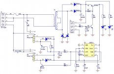
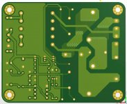
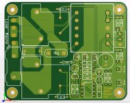
On the current board version seen in the pictures posted by Bob, the Live potential is fused and the neutral is switched by the relays. on the previous versions, both the relays and fuse were connected on Live. I did the change because the previous layout allowed thinner tracks to be routed unless i use copper pour patches with multiple vias, and by increasing the track width, i should decrease the track clearance.
Anyway, a mains switch should be used before the PSS circuit, as the small PSS transformer is permanently connected to mains as long as the board is energized, to allow remote turn-on by simply connecting together the pins 1 and 2 of the small green connector, J2.
i attach for reference the v2 schematic, and layout for reference.
Attachments
I believe there is nothing wrong with inserting the Soft Start in the Neutral. It works just as well as in the Live.
We had a long discussion on the Pros and Cons of these two options, but never reached a conclusion. Maybe 3 or 4 years ago?
Now that we know that the Fuse is on the Live input then that input should be labelled L and the other input should be labelled N (if in the UK). Would North Americans want to see H & C?
Are K1 & K2 swapped?
I don't understand the time delay on K1 making me think the schematic is not what is on the PCB.
Last edited:


What you do require is this symbol on tyour PCB near the mains.
Just the lightening strike symbol shown here:
Shop Safety Signs & Posters Hazard Safety Signs Danger Electric Shock Risk - Safety Signs — The Office Safety Company
It is a recognised symbol for high voltage (that includes mains), and will indicate dangerous voltages.
Creepage and clearance rule:
The Evaluation of Spacings in Electronic Product Design
Andrew, Some here call the neutral "Common" due to the fact that neutral and earth ground connect to the same bus in the service box as shown in the earlier picture. The terms are interchangeable and should not be a problem. Neutral would be the preferred choice.
Last edited:
I'll try to member our LNE (Live Neutral Earth) is equivalent to your HNG (Hot Neutral Ground).
Will all North Americans recognise HNG?
While they will all recognize (Hot Neutral Ground) and H, N, G I'm not at all sure about "HNG".
- Status
- This old topic is closed. If you want to reopen this topic, contact a moderator using the "Report Post" button.
- Home
- Amplifiers
- Chip Amps
- MyRef Integrated Solutions