Here's another very helpful and informative answer from Andrew dealing with the choices available for the relays mentioned earlier. In the future I'll just ask my questions on the forum to avoid transfers and duplication.
"Your american and my english must be different.
4 relays is not the same as a 4way/4pole single relay.
A single pole double throw SPDT
A double pole double throw DPDT
A single pole single throw SPST
A double pole single throw DPST
are the commonly available relays types.
There are a few Quad pole relays, they will be specialized and more expensive.
But a Quad or double pole relay will switch over all contacts at the same time. I think you want some of the relays to have timings or events that do not coincide.
A single pole is effectively 1 switch, whereas a double pole is effectively 2 switches that operate together.
A single throw is one switch that has two positions, Normally closed and Open or Normally open and closed. Be careful ordering single throw relays. You must specify NO or NC depending on what your circuit needs.
A double throw is one switch that has two operating positions. Normally closed and Normally open, swapping to become active open and active closed.
If you use a double pole in lieu of two single pole relays, it is usually cheaper and uses less space and uses less power.
The examples you show are 250Vac 10A and 30Vdc 10A
These would be good for any 115/230Vac mains side switching and also OK for chipamp speaker switching, but not for rail switching, unless the supply rail were less than +-31Vdc.
Now to operating voltage.
A low power coiled relay draws about 500mW, some less and some much more.
A typical 12V relay has ~ 300ohm coil (12^2/300= 480mW)
A 12V pair in series would need 24Vdc and 40mA
A typical 5V relay has ~ 60ohm coil (5^2/60 = 417mW)
4 in series would need 24V and 83mA
A typical 24V relay has ~ 1100ohm coil (24^2/1100 = 524mW)
A DPST NO 24V relay would need 24V and 22mA
This last option gives you 2 NO relays that only need 22mA to hold closed. This holding current can be reduced by half if you adopt a relay current saving circuit.
A pair of 24V DPST NO relays could give 4 switches and need ~ 22mA to hold closed with the appropriate driver circuit.
Now to dual usage of a transformer winding.
I prefer to use a separate transformer for these control/switching/digital uses.
A separate winding is workable, but may transmit more interference into the audio stage.
The same winding is also workable, but it might transmit even more interference into the audio stages.
Look at the quiescent DC current draw of your audio stage fed by your transformer or transformer winding.
Would an extra 20mA to 80mA be a big load in comparison?
Would switching some or all of those relays at the same instant cause an audible electrical click in the power supply?
Now imagine the music current draw on the transformer winding. Do you think that extra 20mA to 80mA would produce an audible electrical click when some or all of the relays switch over? Would it matter if you heard an audible click during that relay operation?
Regards
Andrew T."
* * * * * * *
I was afraid I'd hear about a fifth transformer, but it is a more precise solution than trying to pull relay power from one of the others.
Bob, I got back from my sailing vacation, and sent you a PM in response to your PM. Diagram included, in that PM to you.
If you elect to build your own self-start circuit (and it isn't "rocket science") and want to use a 4 pole single throw relay, here's one suiltable candidate:
OMRON INDUSTRIAL AUTOMATION|G7J-4A-B-W1-DC24|POWER RELAY, 4PST-NO, 24VDC, 25A | Newark.com
If you elect to build your own self-start circuit (and it isn't "rocket science") and want to use a 4 pole single throw relay, here's one suiltable candidate:
OMRON INDUSTRIAL AUTOMATION|G7J-4A-B-W1-DC24|POWER RELAY, 4PST-NO, 24VDC, 25A | Newark.com
Bcmbob,
that was a Private Email to answer your specific Email questions.
You asked previously to share my PM. But you did not ask this time!!!!
There are some typing errors that I cannot get access to correct.
Since it is not my post I cannot reasonably ask the Moderators to substitute the correct text.
that was a Private Email to answer your specific Email questions.
You asked previously to share my PM. But you did not ask this time!!!!
There are some typing errors that I cannot get access to correct.
Since it is not my post I cannot reasonably ask the Moderators to substitute the correct text.
My apologies to you Andrew. I did send you a reply stating my intent to post your answer, and after getting no response from you I regrettably made the assumption you had no objections. I forgot that thing that says "Assume makes an a** out of u & me".
I hope you will notice when posting your answer, I said "in the future I will ask my questions on the forum". That expressed my fear that this exact problem might show in time.
Your contributions are extremely valuable and always informative. I hereby solicit your continued involvement and suggestions on this topic and express my regrets at not being more careful. I will contact the forum admin to request appropriate corrections be made.
I took Uriah's advice for a 90 degree mount for the Lighter Note. I was even able to use the base of the previous bracket. Moved the out posts over 3/4" and changed the RCAs to over/under.
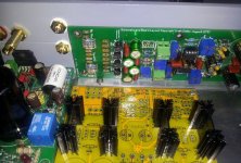
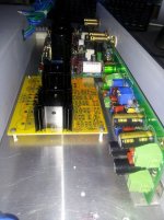
Gained big block of space - hopefully enough for the protection elements.
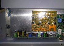
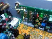
Fake yellow wires demonstrate short path signal travels in one channel.
Next step - let the protection system develop on the thread and squeeze it in as best I can.


Gained big block of space - hopefully enough for the protection elements.

Fake yellow wires demonstrate short path signal travels in one channel.

Next step - let the protection system develop on the thread and squeeze it in as best I can.
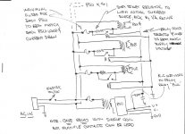
Here is CanAmMan's take on the proposed transformer protection project. This time I got the OK of all involved and hope there will be an active productive discussion here on the board.
************
"I'm back in cold Colorado, and had a chance to digest your thread and AndrewT's comments. Here's my thoughts (and please see the attached).
1. AndrewT is making the case for individual fuses sized to each toroid and power supply. This makes good sense, because if you size to one "mega-fuse" and your smallest power supply goes bad, it may not (in itself) be enough to blow the fuse. That can lead to bad thins for that specific power supply, and your amp in genera.
2. AndrewT is addressing soft start from the "engineering, build your own" perspective. He's right in saying building a custom soft start is easy, and integrating it into your four power supply MyRef is not difficult, if you take the DIY route.
3. See diagram. Andrew is saying take your smallest (and therefore, in theory, your "most safe" power supply, and do NOT use soft start on it. Rather, use it to power it's respective circuits AND POWER A SOFT START controller (see lower right-hand side of the diagram). Let the DC from this power supply serve as the "sense" and power source for your DIY soft start circuit (which can be as simple as a resistor and capacitor in an RC circuit, or perhaps with a simple IC timer (such as an NE555)). The soft start should have an output capable of driving MULTIPLE relays (more on this in a second....), after about 10-20 "cycles" of your main line AC voltage (i.e., for 60 cycle line current, that would be a delay of 10/60=1/6 second, to 20/60=1/3 second).
4. After that appropriate delay, your DIY soft start circuit should then drive ONE relay for EACH of your other amp power supplies. The coil voltages for these relays should be determined by your DIY soft start circuit output voltage--and wire the relay coils in either series or parallel, as to best match your soft start circuit output. In my diagram, I show them as wired in parallel, but obviously, your DIY soft start circuit would have to be able to provide the current draw to energize these relays in parallel.
5. EACH relay then serves as the soft start "delay relay" for each respective toroid. On initial start up, the relay is NOT energized, so initial mains current for each toroid would pass through a resistor, limiting the initial current surge while the toroid flux built, and while the filter caps come up to charge. There's continuing debate if these limiting resistors should be "normal resistors" per se, or if using thermistors (NTC resistors) makes better sense. I'll let the debate continue.
6. After the first power supply (again, lower right hand part of the diagram) is energized, and the soft start circuit puts out its "delayed voltage" to the MULTIPLE relay coils, the contacts on EACH coil are pulled down, thereby bypassing the INDIVIDUAL mains surge-limiting resistors for EACH toroid--and the amp starts normal operation.
7. If you are able to find a rugged relay with MULTIPLE pairs of contacts (suitably rated for your line voltage and current draws) you don't need multiple relays....but remember to handle EACH TOROID individually, with it's own respective limiting resistor and set of relay contacts.
8. Is Andrew's approach overkill? Not necessarily. Use of multiple fuses is great advice, and should NOT be avoided. Use of soft start (particularly on your higher VA circuits) is always a good idea. Is use of "normal" resistors or NTC thermistors best (TBD)? Keep in mind, Andrew's concept, and the circuits in the diagram (attached) are not difficult nor complex to implement--and Andrew is giving you a good, safe, and sound engineering solution. In fact, his solution is pretty elegant, especially if you can find one robust power relay with multiple sets of contacts.
9. Are there other ways to do this? Yep. Individual (commercial, of the shelf) soft start modules can also be used--but at a cost, and at the expense of "real estate" inside your amp chassis.
Hope that helps.
Ken "

Some of the clouds are clearing 🙂. Can someone with MyRef knowledge designate the best place to attach probes to determine quiescent and load currents. If a statement of the design specs for this factor is available, that would also be terrific. The same process , in my case , will be needed for the LN and the JC-2 in order to start building the protection circuit.
in general Chipamps don't give one access to measure the output device bias nor the quiescent current.
You would need to add some low value sensing resistors and measure Vdrop.
This PSU+Chip PCB does not support adding temporary sensing.
You would need to add some low value sensing resistors and measure Vdrop.
This PSU+Chip PCB does not support adding temporary sensing.
Understood Andrew, then what is the method to determine the needed values for the components in the protection circuits? Is it purely calculations, and how important is determining the current swing from quiescent to full bore operation?
Speaker delay is already built in.
I think you are considering adding, soft start.
You need one timer controlling the relays to the transformers for the chipamps.
The resistor value & power are determined by the VA of each of the transformers.
What other protections are you referring too?
I think you are considering adding, soft start.
You need one timer controlling the relays to the transformers for the chipamps.
The resistor value & power are determined by the VA of each of the transformers.
What other protections are you referring too?
I should have been more specific. I'm talking about the pieces in the "transformer protection" circuits - everything before power enters the MyRef,LN and JC-2.
It looks like it will require either a pre-built device like the one I ordered
http://www.connexelectronic.com/documents/Power_SoftStart.pdf
feeding 4 relay & resistor combinations for timing -
OR
several relay/resistor/fuse combinations as described in CanAmMan's diagram. In all cases there appears the need for specific values in many components.
Am I seeing this correctly?
Not sure you are reading it correctly. I will rephrase.
You need one timer.
That one timer is located at the bottom of the diagram and is powered by it's own direct on line starting, low VA transformer.
Now move up the diagram to the lowest of the power transformers.
There is a soft start after the fuse. That soft start is a resistor or thermistor rated for the transformer VA that it is starting. Initially the resistance acts as a current limiter.
After a time delay of a few hundred milliseconds the relay triggers to short out the resistance and the transformer now runs direct from the fuse and mains.
These same two components, relay and resistance, are repeated for each power transformer.
The fuses are not protecting the downstream components.
They are preventing the cables from catching fire and taking your house with them.
Last edited:
Just a minor point, too, on my schematic. In it, I suggested "tapping into" your lowest VA power supply/toroid to steal power for the soft-start circuit. If you have the opportunity, an alternative would be to use a separate power supply just for the soft-start (and then use relay contacts and surge resistors for each and every MyRef power supply/toroid).
I provide the separate power supply as an alternative, because if you use the "industrial grade" Omron relay I suggested (4 pole, single throw, normally open), it's a hefty relay with a not insignificant current draw in the coil. This may or may not be bothersome, depending upon what else is being powered by your "lowest VA" power supply. Your call........
(Besides, if you are already using four toroids in your amp--what's one more, to power the soft-start circuit? 😱 )
Understood Andrew, then what is the method to determine the needed values for the components in the protection circuits? Is it purely calculations, and how important is determining the current swing from quiescent to full bore operation?
The quiescent current is entirely within the LM3886 chipamp - it can only be externally sensed, as AndrewT stated, by adding a sense resistor in series with one of the power traces - either +Vdd or -Vdd. However, the LM3886 has an internal SOA protection mechanism called SPiKe, that can sense both the output voltage swing and the current(s) through the output stage, and force clipping on overload. This is completely inside the chip, and there's no way to monitor or control its operation.
The external protection circuit is merely looking at the DC output offset - if it's too high, it de-energizes a relay and disconnects the speaker from the output, to protect the speaker, not the chip.
Thanks Siva,
I think the word "protection" is muddying the waters. There may already be a EE term for this concept - but I'll try to coin sometime a bit more definitive. How about "Transformer Power-on System" = TPS for future reference on this thread?
Also,it was pointed out that I hadn't posted the VA specs for this project -
T1 = Antek AN-2222 – 200VA for MyRef A
T2 = Antek AN-2222 – 200VA for MyRef B
T3 = Antek AN-0518 – 50VA for JC-2 Pre
T4 = Antek AN-0112 – 10VA for Lighter Note
CanAmMan - What exactly are you abbreviating with "R-C Network" at the left lower side of the diagram? I'm learning to be very hesitant to make assumptions.

Use a timer, not an RC filter.
The major problem with an RC filter is the very variable output voltage that tracks the mains voltage and droops with load current.
The resistor must pass high enough current to ensure positive triggering when voltage is low. That same resistor can run very hot when the voltage is high. The relay will also see all these voltage variations.
Andrew, I'm still a little dull here. You mention "timer" at the start of your last post, and "relay" near the end. Can you clarify?
Also to all - Please note that Ana at the forum admin graciously took on the task of fixing my post of Andrew's eMail in post #21. For clarity, the information Andrew was referring to is included in post #10.
Thanks Ana/admins !
Also to all - Please note that Ana at the forum admin graciously took on the task of fixing my post of Andrew's eMail in post #21. For clarity, the information Andrew was referring to is included in post #10.
Thanks Ana/admins !
- Status
- Not open for further replies.
- Home
- Amplifiers
- Chip Amps
- MyRef Integrated Solutions