bcmbob,
You need something to "delay" the voltage to the soft-start relays.
Two common ways to do this are through a RC circuit (resistor-capacitor) or through a simple IC timer chip:
Andrew's comments are right on, as normal. There's some variability in the consistancy of an RC circuit (normally driven by the voltage applied to the RC circuit), but in a relatively non-critical timing design (which a soft-start usually is....), the variability may not be a factor. The bigger factor (and I haven't run the calculations for a MyRef soft-start), would be the power the RC network would have to supply to "pull in" (and keep pulled in), several relays (or one large hefty relay).
The IC timer chip is another alternative. Typically, the delay timing can be set more accurately, and more repeatedly. In addition, the IC timer can be selected to directly power the relay(s) for each toroid. If the IC timer itself can't handle the current requirements for the relay coils, it's an easy matter to add a transistor that can provide sufficient current to these coils.
I'd go the with IC. THere are probably delay circuits (for the NE555, in particular) available on the internet, or even internal to the DIYAUDIO forums.
Ken
Hi Ken,
I've had in the back of my mind Andrew's reference to using a LM317 back in post #2 but thought it might be a more complicated solution. (Little did I know") ). If you have the time and inclination, another quick sketch would be fantastic. I believe Andrew is also working on a graphic presentation of a useful component. Since we are here it would be fun to gain some knowledge on both approaches.
). If you have the time and inclination, another quick sketch would be fantastic. I believe Andrew is also working on a graphic presentation of a useful component. Since we are here it would be fun to gain some knowledge on both approaches.
As I said earlier I'm attempting to fit all this into the available space in the chassis I'm building. It will be interesting to compare the possible physical layouts of the two approaches - though if needed I can grow this one.
I've had in the back of my mind Andrew's reference to using a LM317 back in post #2 but thought it might be a more complicated solution. (Little did I know
). If you have the time and inclination, another quick sketch would be fantastic. I believe Andrew is also working on a graphic presentation of a useful component. Since we are here it would be fun to gain some knowledge on both approaches.As I said earlier I'm attempting to fit all this into the available space in the chassis I'm building. It will be interesting to compare the possible physical layouts of the two approaches - though if needed I can grow this one.
bcmbob,
In addition, the IC timer can be selected to directly power the relay(s) for each toroid.
Ken
Is it possible to have the timer conduct/interupt the speaker protection circuit ? So the My_Ref can power up but no sound from the speakers until everything else is on ?
If you have the time and inclination, another quick sketch would be fantastic.
Seek, grasshopper, and all things become enlightened:
http://www.diyaudio.com/forums/power-supplies/161723-soft-start-using-lm555.html
RC filter : a device that attenuates some frequencies.
True, Andrew. But the performance of the RC circuit is determined by the time constants of the circuit selected. And as such, and RC circuit is not only useful as a PSU or audio filter.
If you use a suitably large resistor to charge a large capacitor, then you introduce a time delay in the capacitor reaching its maximum charge voltage. Hence, and RC circuit can be used as a delay for a soft-start. Granted, I would not use this for a repeatable and long delay (1+ seconds), but for cheap non-critical delay circuits, it works fine.
Ken
Great link and a new site for future reference Ken - thanks, I'll be studying tonight.
Squalor - I asked a similar question over on the MyRef Build thread. The consensus appears to be - leave the MyRef alone as it's design is closely calabrated as a self-contained package. There was some discussion on changing the value of one resistor to lengthen or shorten the delay in the early stages. The value of that piece in the final BOMs has demonstrated the best performance (of the relay) for those who know the MyRef from a design standpoint. We gotta look elsewhere.
Squalor - I asked a similar question over on the MyRef Build thread. The consensus appears to be - leave the MyRef alone as it's design is closely calabrated as a self-contained package. There was some discussion on changing the value of one resistor to lengthen or shorten the delay in the early stages. The value of that piece in the final BOMs has demonstrated the best performance (of the relay) for those who know the MyRef from a design standpoint. We gotta look elsewhere.
Last edited:
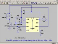
Or........try this one. Note that the author (in German) is stating this is a 100 second delay circuit. The delay is determined by the values of C1 and R1.... You can use the NE555 techsheet to determine C1 and R1 values for a more useful delay (say, .2-.5 seconds). This circuit is "nifty" since it also incorporates a mosfet as a driver for the relay. You should be able to drive multiple relays (or one hefty industrial relay) with this circuit.
Attachments
You'r right CanAmMan - Enlightenment Flows to the Seekers.
Thanks to Dario ( the real Eveready Bunny), we now have access to a soft-start design from Mr.Penasa - the creator of the MyRef - himself.
It is in Italian but Google translate does a great job.
http://www.webalice.it/mauro.penasa/Soft_start.html
Thanks Bunches Dario - and of course Mauro - I'll be up late tonight.
Thanks to Dario ( the real Eveready Bunny
), we now have access to a soft-start design from Mr.Penasa - the creator of the MyRef - himself.It is in Italian but Google translate does a great job.
http://www.webalice.it/mauro.penasa/Soft_start.html
Thanks Bunches Dario - and of course Mauro - I'll be up late tonight.
Last edited:
And, and, as always, Rod Elliott provides a good tutorial, sensible caveats, and a sound solution. (Sound....no pun intended)
Soft-Start Circuit For Power Amps
Soft-Start Circuit For Power Amps
Yep..... interesting to see that the Penasa article in posting #50 also references the Rod Elliott article.
Unclear, if the power "step down" approach Mr. Penasa uses would power the 4 relays (or one large industrial relay) your MyRef would require.
However, having said that (please refer to the schematic in his Italian article) if you replaced his Var1, C3, R2, R3 with a conventional small toroid as a more traditonal "step down" method, then:
.....You're keeping mains circuits (and mains voltages) "outside" of your soft-start circuit (except for your relay contacts),
.....And you effectively end up with a resistor (R1), charging a capacitor (C1)through a diode bridge, with the capacitor slowly (in relative terms) reaching a delayed voltage to trigger the relay. Ergo, this is effectively the simple RC network delaying operation of the relay that I had talked about earlier.
(I just remain safety concerned, about using VAR 1, C2, R2 and R3 to circumvent the need for a transformer to step down the mains voltage to operate this circuit. Sure, it's possible, but............)
I'm going to take a day or so to digest everything that has flowed forth. Drilling down to the best configuration is obviously the next step. In the meanwhile, it would be nice to hear from others who might be considering an integrated - even a receiver build.
Come one -Come All.
Come one -Come All.
not an RC filter.
The major problem with an RC filter is the very variable output voltage that tracks the mains voltage and droops with load current.
The resistor must pass high enough current to ensure positive triggering when voltage is low. That same resistor can run very hot when the voltage is high. The relay will also see all these voltage variations.
..............If you use a suitably large resistor to charge a large capacitor, then you introduce a time delay in the capacitor reaching its maximum charge voltage. Hence, and RC circuit can be used as a delay for a soft-start. Granted, I would not use this for a repeatable and long delay (1+ seconds), but for cheap non-critical delay circuits, it works fine.
Or........try this one. ..... You can use the NE555 ............ This circuit is "nifty" since it also incorporates a mosfet as a driver for the relay. You should be able to drive multiple relays (or one hefty industrial relay) with this circuit.
the statements made by Can Am do not recognise the "problem" as specified in my post..................And you effectively end up with a resistor (R1), charging a capacitor (C1)through a diode bridge, with the capacitor slowly (in relative terms) reaching a delayed voltage to trigger the relay. Ergo, this is effectively the simple RC network delaying operation of the relay that I had talked about earlier.............
A simple RC does not work well.
A 555 uses an RC in a circuit that is designed well and performs well as a timer.
One can mimic the 555 timer action of the RC, using discrete.
The post shows the relay and mosfet switch powered from the same supply as feeds the 555. The relay and mosfet can be fed from a separate supply selected to drive the relay rather than to not overload the 555.
Hi Bob, first of all, I wanna commend you for your great effort. awesome work!
I am planning on building a receiver setup for my dad but this doesn't concern myref, and it's much more of a bare-bone solution than yours.
it will be a 1543x4 nos dac coupled with a tripath integrate. lipo for dac and ex-psu for the amp.
the only benefit I see from this config is the elimination of interconnects, besides providing the much needed ergonimics for my dad who still struggles even with a home theater receiver
Presapian - Thank you for your kind words. Having fun and learning lots.
Have you made a selection for your receivers FM function? I see there is everything from super-small prebuilt modules to fairly sophisticated full kits.
Though I put "MyRef" in the thread title, it hopefully will be seen as a focus and not a limitation. The small footprint of two BrianGT (Chipamp.com) amps powered by one PS kit and a single transformer could form the heart of a very good and compact integrated or receiver build.
Tell your Dad he's doing OK. I'm convinced all the major HT equipment manufacturers have a group of engineers dedicated to making the end user feel dumb.
Last edited:
Progress on my project is slow. I do have the heatsinks attached to the steel part of the chassis and have a IEC mounted but not a fuse holder. I have some wood work done, my amp has a face but no sides or top. It's been rainy and I've been playing Skyrim.
The Sure IR receiver and remote arrived today and the stepper motor controller arrived a few days before that. I've had Uriah's LDR kit for over a week but have not populated yet. My next step is to order the Alps pot and the parts for the Regi22 PSU's
I don't know how many psu's to make. I need to power the LDR volume, the stepper controller, the IR receiver, the Alps pot and a Twisted Pear Darwin source selector. All require +5V so can I run parallel leads from one PSU to all of these ? Are all these currents DC ? I'm just trying to Arrange Whatever Pieces Come My Way.
squalor - your funny. Hopefully one of the members will provide better information, but I modified a PC power supply for a product I sold years ago - The Bomac Tower for Amiga computers. I found all the wires came from two pads on the PS motherboard - one for 5VDC and one for 12VDC. If you have an old PC PS open it up and take a look.
It's a little late to the game, but I believe Uriah has (or is developing) a product the combines many of the functions of your modules. Shoot him a PM if you haven't already.
It's a little late to the game, but I believe Uriah has (or is developing) a product the combines many of the functions of your modules. Shoot him a PM if you haven't already.
Last edited:
Squalor
There is no need to use more than one 5V supply as long as the one you build can carry the current needed for your multiple 5V projects. You could run a LM7808 into a LM317 and take the 8V down to 5v and have a pretty quiet supply. Dont forget to put some capacitance on the input and output of the LM317. Actually, Maybe go with a LM7812, then a LM317 and then a diode after capacitance to each project. Voltage will drop over the diode but it will eliminate a lot of interaction between the 5V projects. It important for the LDR supply to be clean. If the others dirty it up it wont be as great as it could be.
I do have a LDR input selector. I dont have it on my site because I only sell it when people ask about it. I bought only 30 of them. Here is a link to the description:
https://picasaweb.google.com/udailey/InputSelectorBuildGuide?authuser=0&feat=directlink
If when you complete this project you end up loving LDRs you might try this little guy to replace your input resistors:
https://picasaweb.google.com/udailey/ResistorReplacer?authuser=0&feat=directlink
- Status
- This old topic is closed. If you want to reopen this topic, contact a moderator using the "Report Post" button.
- Home
- Amplifiers
- Chip Amps
- MyRef Integrated Solutions