Did you ever consider swapping D1 & D2 with the largest chokes that would be able to fit in there?
...
Might be worth a try. Maybe one of the readers here with more test equipment could do some measurements.
The PS schematic you attached it's not the current one.
The FE LM318 PS don't have those diodes and 470uF caps, the linked schematic include a modification proposed by UnixMan which probably will not be included for space constraints.
For the same space problems I don't think it's possible to include chockes either...
The PS schematic you attached it's not the current one.
That's the one you attached to message #303 on Feb 2.
The FE LM318 PS don't have those diodes and 470uF caps, the linked schematic include a modification proposed by UnixMan which probably will not be included for space constraints.
For the same space problems I don't think it's possible to include chockes either...
<Sigh> Okay, please direct me to the current one...

<Sigh> Okay, please direct me to the current one...
On this GoogleDocs folder you can find all about the My_Ref Fremen Edition
Last edited:
On this GoogleDocs folder you can find all about the My_Ref Fremen Edition
I get an Error 404 Not Found message.
I get an Error 404 Not Found message.
I know and I can't understand why...
BTW I've attached it.
PS
Now it seems to work... let me know if it works also for you
Attachments
Last edited:
I know and I can't understand why...
BTW I've attached it.
PS
Now it seems to work... let me know if it works also for you
Works here now too. Very strange.
ALso, what is part SJ-1? It's attached to pin 7 of the LM3886 and I don't see it in the BoM.
what is part SJ-1? It's attached to pin 7 of the LM3886 and I don't see it in the BoM.
You can't see in the BOM since it's a solder jumper on the PCB...
It allows to ground LM3886 alternatively to power ground (like in My_EVO Rev A) or signal ground (as in My_Ref Rev C).
You can see it the PCB jpeg.
The PS schematic you attached it's not the current one.
The FE LM318 PS don't have those diodes and 470uF caps, the linked schematic include a modification proposed by UnixMan which probably will not be included for space constraints.
How about trying the cap-choke-cap DC smoothing circuit on your breadboard model and listening for any differences.
Also, any pictures of your completed boards or interim breadboard place in your Google Docs folder would be instructive.
Last edited:
CLC PS Preconditioners
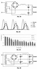
VladimirK said: I would like to attract attention once again to chokes in power supplies of AB amps. Maybe some substractions from a textbook (its in russian) could help me to explain the point: chokes (10mH and more) help a bit to have more favorable spectrum of charging pulses, but they do increase voltage drops at filter capacitors during current consumption peaks and affect negatively sound dynamics.
As a conclusion, chokes are not recommended for AB amps, except for maybe configuration shown in fig.36, with external or well screened part of PS, and with abnormally big C3 and C4 (in order to compensate negative effects of chokes)
John Curl added: http://www.diyaudio.com/forums/analog-line-level/146693-john-curls-blowtorch-preamplifier-part-ii-1916.html#post2818214 Message #19154
In the present case, the supply after the initial takeoff points that feed the LM3886 (V+/V-) then feeds the LM318 (14V+/V-), which is a relatively low current device. The CLC (the "pi filter") is an effective filter in this condition and has over half a century of use in quality audio equipment.
An alternative would be the LM317/337 series regulators, feeding LM317/337 current regulators, feeding a final shunt regulator. I think that's the right order - working from memory here.
It's all in the name of quiet DC for the project.
Chokes might be okay for high frequency digital devices, but it may not have positive effects in audio frequency. Rather, the additional components may prove to degrade the quality. Maybe there is a good reason to use it here?
VladimirK said: I would like to attract attention once again to chokes in power supplies of AB amps. Maybe some substractions from a textbook (its in russian) could help me to explain the point: chokes (10mH and more) help a bit to have more favorable spectrum of charging pulses, but they do increase voltage drops at filter capacitors during current consumption peaks and affect negatively sound dynamics.
As a conclusion, chokes are not recommended for AB amps, except for maybe configuration shown in fig.36, with external or well screened part of PS, and with abnormally big C3 and C4 (in order to compensate negative effects of chokes)
John Curl added: http://www.diyaudio.com/forums/analog-line-level/146693-john-curls-blowtorch-preamplifier-part-ii-1916.html#post2818214 Message #19154
In the present case, the supply after the initial takeoff points that feed the LM3886 (V+/V-) then feeds the LM318 (14V+/V-), which is a relatively low current device. The CLC (the "pi filter") is an effective filter in this condition and has over half a century of use in quality audio equipment.
An alternative would be the LM317/337 series regulators, feeding LM317/337 current regulators, feeding a final shunt regulator. I think that's the right order - working from memory here.
It's all in the name of quiet DC for the project.
Attachments
How about trying the cap-choke-cap DC smoothing circuit on your breadboard model and listening for any differences.
I can do it for sure but until next month I don't have money to invest...
Also, any pictures of your completed boards or interim breadboard place in your Google Docs folder would be instructive.
If you'referring to Rev C you can see them in the tutorial.
At post 321 I've attached a pic:
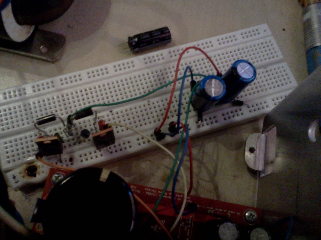
It's the LM318 PS with UnixMan Mod
Fine tuning is instructive...
This LM318 PS is a very instructive bench!
I felt that something was wrong with latest incarnation of the FE PS so I've tried to go back to BZX85 zeners, much better, more dynamic and entertaining.
The 1N53xx sounds in the FE PS too much warm and not as dynamic as the BZX85.
So, as a check, I've rebuilt the original My_Ref simple shunt.
It sounds good but not as refined and controlled as the FE PS (both with BZX85s)
Then I've tried to swap (in the My_Ref original shunt) the BZX85 with 1N53xx: much, much better!
Not as better as the FE PS but a worthwhile improvement.
So why in the simple shunt sounds better the 1N53xx and in the FE PS the BZX85?
The main difference is the current flowing through the zener...
Now let's analyze the thing (please Andrew, correct me if I'm doing any mistake).
In the FE PS R104/R204 regulates the current that flows in the Zener, so it actually partition the current between it and the shunt transistor.
The Zener current is calculated:
Vbe/R104
So for 270 and BC639/DB139 it meas 1V/270R = 3.7mA
The LM317 CCS current is calculated dividing LM317 VRef by R101/R201:
1.25V/51R = 24.5mA
So, if LM318 draw 5mA in the transistor flows 24.5-5-3.7 = 15.8mA.
In the original shunt the generated current is the voltage on R1/R4 (35V- Zener voltage = 23V) divided by its value (1K):
(35V-12V)/1K = 23mA
So in the zener flows 23ma-5ma = 18mA
Thus it seems that the 1N53xx needs more current to work at its best...
Now I've to decide if it's better to increase the Zener current (and thus the LM317 CCS current) increasing also heat generation or simply use the BZX85s
Any opinion on it?
Last edited:
Hope you have good luck with it.VladimirK said: I would like to attract attention once again to chokes in power supplies of AB amps. Maybe some substractions from a textbook (its in russian) could help me to explain the point: chokes (10mH and more) help a bit to have more favorable spectrum of charging pulses, but they do increase voltage drops at filter capacitors during current consumption peaks and affect negatively sound dynamics.
As a conclusion, chokes are not recommended for AB amps, except for maybe configuration shown in fig.36, with external or well screened part of PS, and with abnormally big C3 and C4 (in order to compensate negative effects of chokes)
John Curl added: http://www.diyaudio.com/forums/analog-line-level/146693-john-curls-blowtorch-preamplifier-part-ii-1916.html#post2818214 Message #19154
In the present case, the supply after the initial takeoff points that feed the LM3886 (V+/V-) then feeds the LM318 (14V+/V-), which is a relatively low current device. The CLC (the "pi filter") is an effective filter in this condition and has over half a century of use in quality audio equipment.
An alternative would be the LM317/337 series regulators, feeding LM317/337 current regulators, feeding a final shunt regulator. I think that's the right order - working from memory here.
It's all in the name of quiet DC for the project.
CLC is a good filter, but it is used to decouple the the load from the source. Sure, you will see less ripple at the rectifier side of the filter, but that is all. If you know of any great commercially available preamp that uses this concept, I certainly would like to give it a try. Works good as a mains line filter, where this configuration is very common. But think about a 10Hz signal draws power and how the charge changes in the cap. Certainly does not make sense to me.Darth,
are you for or against a properly designed C [L+R] C for PSU supply
or is your preference for rC only when suppling a ClassAB amplifier?
For, obviously.
"Properly Designed" - that's the problem. In my previous experience, both can be used for AB amp circuits but the current draw was the issue. In the Tube Era, you had much less current to deal with but much higher voltages. An LC filter provided "quieter" DC than a CLC pi filter at the expense of a predictable voltage drop, which could be useful for preamp designs. The CLC filters had less of a problem with voltage drop and handled the higher current of output tubes better. Remember, though, that "higher current" was still only a few hundred milliamps at most back then.
In any case, the CLC is an inexpensive way to pre-filter the DC so that the active regulators have less voltage swing, ripple, to deal with. I suspect that this would result in better performance for the regulators, but have no proof as I don't have any real test equipment to measure the results.
Anyone who wants to try this for themselves can simply wrap some enameled wire around a ferrous screwdriver shaft and insert it temporarily into the circuit. I just leave the wire on the bobbin it came on - sort of an air-core inductor that doesn't waste the wire.
My suggestions to this thread are just some ideas to try; they've worked in the past and the laws of physics haven't changed in the mean time. Yes, this particular idea is bulky, unwieldy, and visually unappealing, but it's just an idea. In my mind, it's a simple way to improve a power supply without throwing even more active (and expensive) regulators into the mix.
Hope you have good luck with it.
I have, for many years.
CLC is a good filter, but it is used to decouple the the load from the source. Sure, you will see less ripple at the rectifier side of the filter, but that is all.
What would be the effect of less ripple for the active regulators to manage? I don't know for sure, but maybe you could give it a listen and tell us. It's very easy to do.
If you know of any great commercially available preamp that uses this concept, I certainly would like to give it a try.
Ahem. Since when is "commercially available" an indication of quality?
At one time, all commercially available preamps and most amps used this circuit.Works good as a mains line filter, where this configuration is very common. But think about a 10Hz signal draws power and how the charge changes in the cap. Certainly does not make sense to me.
Try it and see (or, listen). It's cheap to make and you probably already have all the parts on hand.
I have, for many years.
What would be the effect of less ripple for the active regulators to manage? I don't know for sure, but maybe you could give it a listen and tell us. It's very easy to do.
Ahem. Since when is "commercially available" an indication of quality?
Try it and see (or, listen). It's cheap to make and you probably already have all the parts on hand.
Since all commercially available preamps used this at one time, then it should not be difficult to name one. Or maybe you can give a clue as to what year and before?
Let's say, it takes in the magnitude of 0.3mH, 1uF to filter 1MHz, to filter anything like 100Hz and below, what would it take?
I think you are doing something that seems to work but do not know why it works. Or maybe you could elaborate on this concept by some example numbers and the related filtering frequency? I am talking about getting at least 10db better in ripple performance.
Last edited:
Since all commercially available preamps used this at one time, then it should not be difficult to name one. Or maybe you can give a clue as to what year and before?
Okay, many pre amps and a lot of amps. Marantz 1,2,5,8&9; Leak 12, 25, 25a, 50+ & Stereo 60; McIntosh MC 40, 45, 60, 240 & 275; AudioNote Conquest 300B, Ankoru, & Quest; Carver Super7; Conrad-Johnson MV-75; Harmon Kardon Citation 1 & 2; most of the Dynaco tube line; and so on. Most are from 1970s and before.
Let's say, it takes in the magnitude of 0.3mH, 1uF to filter 1MHz, to filter anything like 100Hz and below, what would it take?
Since you know the math, what's the result for two 5,000uf caps (just to save a little money and PCB space) and a 20 mH inductor. Or point me to a usable pi filter calculator on the web; one that uses milliHenries and uF.
I think you are doing something that seems to work but do not know why it works.
I'm pretty clear on how chokes and caps work, and why they start to misbehave beyond certain limits. Ever see an electrolytic cap pop due to inductive heating? I have.
Or maybe you could elaborate on this concept by some example numbers and the related filtering frequency? I am talking about getting at least 10db better in ripple performance.
Again, I don't know the formulas w/o looking them up, and it's not all that necessary. Give it a try, give an opinion. Quit playing with numbers and listen to the result.
I don't see any benefit considering the PCB space and total volume it takes. I think you can get a MyRef and try it out for yourself. I am not even convinced how good the CCS in this thread is going to work, but since Dario was committed enough to put out a PCB, plus there are other things I wanted to compare, so I am willing to try it. Maybe that is what you should do to try your idea first with this circuit.
Basically, I put high trust in listening tests and measurements combined. For pure listening, if I cannot see good description on the changes claimed to be improvements, type of music variation enough to be convincing, then I would have to have listened with the person in some sessions to really understand what one calls an improvement. Otherwise, the theoretical aspects need to be convincing enough for me to try, which in this case, it is not.
Let's not forget that large inductors also have large series resistance, when you put these in series with the power taking source impedance into consideration, no matter what the current is, you are going to have a voltage drop that interacts with currents. Not a good idea. Calculators do not take these reality issues into factor.
Last edited:
- Status
- This old topic is closed. If you want to reopen this topic, contact a moderator using the "Report Post" button.
- Home
- Amplifiers
- Chip Amps
- My_Ref Fremen Edition - need help on PCB evaluation