forget about the PSU own ripple. That's just uncorrelated noise. What matters most is the audio freq modulation imposed by the 3886 on the raw PSU rails. That will go all the way up to 40KHz and more. And what's worse is that it is correlated noise. Which is much worse WRT our perception (low level uncorrelated noise is easily ignored by our earing system, while even the smallest levels of correlated noise will affect sound perception somehow).The regulator does best on the 20 kHz ripple, but worst on the harmonics. OTOH, the plain zener does worst on the 20 kHz ripple, but best on the harmonics.
BTW: if you try the cascoded (dual FET) CCS, things will be much better.
")
P.S.: don't forget to add the Diode-Cap trick *before* the CCS. Even that alone will do wonders.
Last edited:
no way. That's a couple of Enhancement MOSFETs, you need Depletion devices.Maybe something like this dual fet could help...
well, for this purpose you may consider the maximum possible current absorbed by the load (318+Zener or shunt reg) in the worst case and assume R=V/I.
...
In practice, I guess that something >= 470u (perhaps 1000u) 50V would do just fine.
Wow, thanks!
That's the same one!Sorry, I thought it was clear.
It was clear, I've pointed to the second schematic since it included only the two CCSs
you only need 2 FETs and 3 Rs for each CCS. For this application heatsinks are probably not required (and perhaps not even TO220 FETs).
Exactly and since the PS includes two CCSs (one per rail) it makes 4 FETs and 6 resistors...
Please remember me, how much current is drawn by the 318? how much by the shunt reg?
The LM318 needs circa 5 mA and at least 10-12 mA for the shunt.
To maintain Rev C original current 23mA are needed.
Which is much worse WRT our perception (low level uncorrelated noise is easily ignored by our earing system, while even the smallest levels of correlated noise will affect sound perception somehow).
Very interesting... BTW even the LM3x7 CCS gave a not small improvement
BTW: if you try the cascoded (dual FET) CCS, things will be much better.
I'm sure of that, the problem is how to squeeze them in the PCB...
P.S.: don't forget to add the Diode-Cap trick *before* the CCS. Even that alone will do wonders.
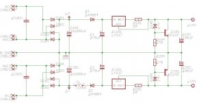
See the attached schematic, is it what you mean?
Is so I can try it this evening.
no way. That's a couple of Enhancement MOSFETs, you need Depletion devices.
Any idea on a similar device with depletion MOSFETs?
Are TO92 ones suitable?
I was thinking about this one
Attachments
Last edited:
I still question whether this is the reason for better performance for the following reasons:The CCS keeps the current from the main (LM3886) PSU rails constant, regardless of spikes/dips in the rail voltage caused by the LM3886. It keeps the voltage contamination on the chipamp rails from reaching the +/- 12V shunt regulator, thus improving the ripple rejection of the shunt regulator. The best CCS would be an N-ch depletion-mode TO220 MOSFET with a Vds max of at least 50V, preferably 100V.
1. The amount of voltage drop across the LM3886 PS rails depend on total current consumption and the PS source impedance. Consuming a constant current load to the PS rail means that the LM3886 PS will be effected more because of the total current consumed under.
2. Taken the PSRR of devices, the voltage drop on the rails would create little effect on the audio performance.
Depending on how the exact improvement in audio one can describe, there must be some other explanation.
Let's assume that we add the LM3886 power in the spice model and put a current load on the LM3886 power to simulate LM3886 active loading, I don't think it will create much variation on the LM318 power; if we then calculate this in terms of PSRR, the numbers would go really low.
I am curious, however, when the term "improvement" or "better" is used in terms of listening, does it imply for a specific track of music, specific album, specific type of music, or a vast mixture of the above? Is it listening at just one volume setting, or a variety of volume settings? I ask this because it is my experience that some modifications may sound better under certain situations, but may sound worse for others. I remember that my active speakers sounded good at low and moderate volume settings, the higher volume I get to, the more fatiguing it becomes; after the power supply cross rail capacitors I applied, the overall sound becomes quieter, yet more penetrating, and I can turn the volume up close to max without so much feeling of fatigue. The same is applicable to the original MyRef.
1. The amount of voltage drop across the LM3886 PS rails depend on total current consumption and the PS source impedance. Consuming a constant current load to the PS rail means that the LM3886 PS will be effected more because of the total current consumed under.
I can't follow you...
If you absorb a constant current, which BTW is several order of magnitude lower, how can this affect LM3886 power more than a changing current?
2. Taken the PSRR of devices, the voltage drop on the rails would create little effect on the audio performance.
I think that must be taken in account the fact that the PSSR is not constant at different frequencies.
But is this effect audible? I think so.
I am curious, however, when the term "improvement" or "better" is used in terms of listening, does it imply for a specific track of music, specific album, specific type of music, or a vast mixture of the above? Is it listening at just one volume setting, or a variety of volume settings?
All of the above, I think that the CCS improves performance, and not by slight margin, with a variety of different music and at all volume settings.
oh, right.Exactly and since the PS includes two CCSs (one per rail) it makes 4 FETs and 6 resistors...
of course... some attenuation is surely better than none at all!Very interesting... BTW even the LM3x7 CCS gave a not small improvement
use a larger PCB?I'm sure of that, the problem is how to squeeze them in the PCB...
or perhaps you may move the main raw supply (bridges and the larger ElCaps) to a separate PCB to free up some space... 
exactly.See the attached schematic, is it what you mean?

great. With CCS and regulator its effect should be less evident than in my previous applications (on unregulated supply for tubes), but should be worth doing anyway. In principle the effect should be more evident at high volume and/or with hard loads (large output current peaks->deep supply rail modulations). Let me know how it goes!Is so I can try it this evening.
I have no idea. Let' try Googling...Any idea on a similar device with depletion MOSFETs?
Most of the voltage drops only on one of the two FETs, which thus is also the one that takes most of the dissipation. The other can surely be a small device (TO92 or even SMD).Are TO92 ones suitable?
should be good. Or also an LND150. Running some simulations to optimize the design would be a good idea.I was thinking about this one
Last edited:
use a larger PCB?
Sadly this is not an option, I'm limited, with my Eagle license, to 100x160 mm PCBs
or perhaps you may move the main raw supply (bridges and the larger ElCaps) to a separate PCB to free up some space...
I would avoid to split the star ground center out board.
great. With CCS and regulator its effect should be less evident than in my previous applications (on unregulated supply for tubes),
...
Let me know how it goes!
Sure
Most of the voltage drops only on one of the two FETs, which thus is also the one that takes most of the dissipation. The other can surely be a small device (TO92 or even SMD).
Which one of the two is the one suitable for TO92?
should be good. Or also an LND150. Running some simulations to optimize the design would be a good idea.
Fine, the LND150 seems a very interesting one but isn't it limited to 1.6mA as a CCS?
given the particular nested feedback design of this amplifier, the output sound depends mostly on the first stage (LM318). Thus, having it working in the best possible conditions is paramount for the overall SQ.I still question whether this is the reason for better performance for the following reasons:
The PSRR figure of op-amps is unfortunately very misleading. It depends almost entirely on NFB. The spectacular figures which are often reported refers to very low frequencies, were the open-loop gain (and thus NFB) is at its maximum. Unfortunately, the open-loop gain decrease steadily with increasing frequency and the PSRR drops accordingly. In most cases, PSRR becomes very poor already at a few KHz... exactly where it does matter most for SQ!
Clave's link to Mouser brings up the DN2530.
I know now that this is a depletion mode mosfet.
But how does one read the Mouser details to find out what type of mosfet this is?
How does one identify the depletion mode devices from among the hundreds of thousands listed in the various catalogues?
I know now that this is a depletion mode mosfet.
But how does one read the Mouser details to find out what type of mosfet this is?
How does one identify the depletion mode devices from among the hundreds of thousands listed in the various catalogues?
Sadly this is not an option, I'm limited, with my Eagle license, to 100x160 mm PCBs
maybe it's time to switch to some unlimited free software alternative?
KiCad EDA Suite
if you have a large enough local by-pass, you can also keep the star center on the board. Though I don't see much problems running a few twisted pairs from the main board to the raw PSU one.I would avoid to split the star ground center out board.
the "lower" one (in the diagram).Which one of the two is the one suitable for TO92?
Ops... right. Idss way too low.Fine, the LND150 seems a very interesting one but isn't it limited to 1.6mA as a CCS?
Last edited:
very good question... that's what also I would like to know!How does one identify the depletion mode devices from among the hundreds of thousands listed in the various catalogues?
(unfortunately, I'm afraid there's simply no way
).Now, if we are able to make the + & - rails move in the same direction, that means we would effectively created a canceling effect. This is probably why the cross rail capacitors might be effective.given the particular nested feedback design of this amplifier, the output sound depends mostly on the first stage (LM318). Thus, having it working in the best possible conditions is paramount for the overall SQ.
The PSRR figure of op-amps is unfortunately very misleading. It depends almost entirely on NFB. The spectacular figures which are often reported refers to very low frequencies, were the open-loop gain (and thus NFB) is at its maximum. Unfortunately, the open-loop gain decrease steadily with increasing frequency and the PSRR drops accordingly. In most cases, PSRR becomes very poor already at a few KHz... exactly where it does matter most for SQ!
no way. You're drawing current (stealing energy) from the capacitors, thus the voltage will always "shrink".Now, if we are able to make the + & - rails move in the same direction, that means we would effectively created a canceling effect. This is probably why the cross rail capacitors might be effective.
But how does one read the Mouser details to find out what type of mosfet this is?
I've simply wrote 'depletion mosfet' in the 'Part No. / Keyword (English Only)' field...
Maybe I've been lucky...
I've briefly tried KiCad but Eagle, IMHO, is far easier to use and has better libraries support.
Maybe I'll give it another chance in the future...
if you have a large enough local by-pass, you can also keep the star center on the board. Though I don't see much problems running a few twisted pairs from the main board to the raw PSU one.
It's probably so but also Penasa, if I remember correctly, in one of the emails we exchanged was toward the single PCB approach.
Last edited:
Well, if the charge across a cap is reduced on the positive side, then it also becomes less negative on the other side, both side shrink toward 0. This is why this is used to reduce differential noise. Since shrinking on each rail causes opposite voltage at the output, there becomes a nulling effect.no way. You're drawing current (stealing energy) from the capacitors, thus the voltage will always "shrink".
Last edited:
right. But the voltage drop may still create other problems (N.B.: I'm not against the idea of adding a rail-to-rail cap).Well, if the charge across a cap is reduced on the positive side, then it also becomes less negative on the other side, both side shrink toward 0. This is why this is used to reduce differential noise.
See the attached schematic, is it what you mean?
Is so I can try it this evening.
Just tried it with 1N4007 diodes and 220uF 50V Elna RJH (what I've on hand) and something must be wrong...
Can you check again the schematic I've attached earlier?
Sound stage is smaller, sound seems somewhat more 'live' but bass loose precision and distortion is clearly increased...
maybe I've found the problem... possibly the low-esr Elnas upset something in the regulator.
Tried again with 220uF 100V BC 038 and the 'distorsion' is gone...
Also soundstage and bass definition are back, it remains the more 'live' sound.
I must listen carefully to the difference with more different music but at first glance I prefer without this D-C net, with it it sounds somewhat more confused... I don't know....
really strange.I must listen carefully to the difference with more different music but at first glance I prefer without this D-C net, with it it sounds somewhat more confused... I don't know....
 The schematic is correct. Are you sure that you have actually connected everything according to the schematic? (make sure the 3886 is actually connected before the diodes!).
Perhaps the 220u are a bit too small? Don't you have any larger ones?
You may also want to try a rail-to-rail cap after the diodes (with or without the two C to gnd as well; use large values, specially when you have only the rail-to-rail cap).
The problem may also be the new circuit layout. Where is the cap common ground point connected? consider that with the cell the currents on the 318 closes on that point rather than on the general star ground as they did before (using only a rail-to rail cap after the diodes should restore the previous situation WRT ground currents layout).
Just in case, you may also want to try some different diodes types if you have some at hand.
BTW: do you have a scope? can you check the differential voltage across the diodes while driving a real (or real-like) load at normal listening levels?
- Status
- This old topic is closed. If you want to reopen this topic, contact a moderator using the "Report Post" button.
- Home
- Amplifiers
- Chip Amps
- My_Ref Fremen Edition - need help on PCB evaluation