Dario, what is the voltage rating on you power supply large caps?
I'm using Mundorf AG 10000uF 63V, very good (and pricy) caps.
I've used also Panasonic TS-HA 10000uF HA 50V, also very good but Mundorfs are fantastic.
Consistent with previous experience of mine, it seems that higher voltage rating sound better. I'm not sure how much increased voltage rating till the sonic advantage does not increase so much. This might also relate with the current duty cycle rating. Physically, it seems the larger the capacitor, also the better; but there is also probably a limit. Moving from a 63V rated cap to an 80V cap seem to put the image depth, dynamics, image focus, etc. into a more accurate perspective for me. Initial impression would be reduced volume, but under more detailed listening, it's the reduction of undesirable harmonics the sound fatiguing at higher volume settings. I have been able to turn the volume to maximum on my sound card and still be able to bear it.
Seems a possibility to explore with minimal price impact for the DIYer.
Seems a possibility to explore with minimal price impact for the DIYer.
Last edited:
Consistent with previous experience of mine, it seems that higher voltage rating sound better. I'm not sure how much increased voltage rating till the sonic advantage does not increase so much. This might also relate with the current duty cycle rating. Physically, it seems the larger the capacitor, also the better; but there is also probably a limit. Moving from a 63V rated cap to an 80V cap seem to put the image depth, dynamics, image focus, etc. into a more accurate perspective for me.
For sure higher voltage rating (for the same make/model) implies higher ripple current capability and lower dissipation factor.
It's for this reason that I've buyed 63V ones vs 40V ones of the Mundorfs
Seems a possibility to explore with minimal price impact for the DIYer.
The 30mm diameter constraints limits the possibilities, the 80V Mundorfs are 35mm for example.
After a succesful beta maybe for the final version I could manage to provide 35mm posistions.
Do you notice any change in the turn on and shut down times using the different PS large caps? The last change I made seemed to increase the turn on and shut down times.
I have noted that sometimes, changing components, it seems apparent a slight change in the time the relay kick-in.
But I can't say for sure.
BTW it seems logical that bigger caps take sligtly more time and current to complete their charge thus influencing the time of charge of speaker protection's caps, maybe.

I've just swapped the BZX85 zeners with the 1N53xx suggested by Siva and included in the FE BOM...
Very nice improvement...")
Probably in the final version also shunt transistors will be changed to BD139/140, same pinout and similar hfe but rated for higher power handling so that 'hot-rodding' the shunt with more current will be possible.
Another benfit from BD139/140 is they make some more room for 35mm smoothing caps.
Very nice improvement...
Probably in the final version also shunt transistors will be changed to BD139/140, same pinout and similar hfe but rated for higher power handling so that 'hot-rodding' the shunt with more current will be possible.
Another benfit from BD139/140 is they make some more room for 35mm smoothing caps.
a simple trick to improve things a lot (at almost no cost) is the use of a "D-C" cell (series diode/capacitor to gnd; like an RC filter cell, with a diode in place of the R) between the raw supply and the regulator. That will act (almost) like an independent raw PSU which will prevent the 318 raw supply from following the voltage drops imposed by the 3886 on the main raw supply.My goals (in part inspired by Mauro's recommendations on a private e-mail) were:
- isolate LM318 from LM3886's PS pollution (mostly current, I suppose)
- isolate LM3886 PS lines from LM318's PS pollution (mostlly voltage, I suppose)
For absolutely best performance, also add a CCS between the D-C and the shunt regulator. You can use a trivial CCS made with a depletion MOSFET or -better- two of them in cascode.
Last edited:
a simple trick to improve things a lot (at almost no cost) is the use of a "D-C" cell (series diode/capacitor to gnd; like an RC filter cell, with a diode in place of the R) between the raw supply and the regulator. That will act (almost) like an independent raw PSU which will prevent the 318 raw supply from following the voltage drops imposed by the 3886 on the main raw supply.
Seems interesting...
How do you size it?
Which sort of diode?
For absolutely best performance, also add a CCS between the D-C and the shunt regulator. You can use a trivial CCS made with a depletion MOSFET or -better- two of them in cascode.
The FE PS already has a CCS (LM317 based), do you mean a second one?
Attachments
For absolutely best performance, also add a CCS between the D-C and the shunt regulator. You can use a trivial CCS made with a depletion MOSFET or -better- two of them in cascode.
Brilliant idea - simulates great! I plugged in a J310 N-ch JFET in series with R1. Current adjustment with 47R..100R resistor in source leg of JFET - 15..20 mA should be OK. Ripple reduction at 20 kHz is nearly 40-45 dB better. These are quick and dirty numbers, it should be possible to optimize it further. It's so good that I'd like to retrofit it in my completed boards right away. Edit: Dario's LM3x7 CCSes are even better, because R1,R4 which occupy a lot of space are eliminated.
Last edited:
much like a normal PSU. For the capacitor, choose a value that makes Xc@10Hz negligible WRT the (minimum) impedance of the attached load. Within reasonable limits, the larger the better.How do you size it?
Ditto. In this case, just about any diode will do. It's probably better to use some Schottky to avoid reverse-recovery noise.Which sort of diode?
Oh, sorry, forgot about that. I had in mind the original my_ref.The FE PS already has a CCS (LM317 based), do you mean a second one?
Yet I'd prefer the cascoded FET CCS to the 3 pin reg CCS. The latter may show better specs @ low freqs but, given the limited gain/bandwidth of the internal op-amp, I doubt about their performance with increasing freq. And I like KISS.
(yes, 3-pin LOOKS simpler, but inside the chip there's a lot more...).
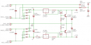
To made it clear, suggested CCS is something like this (of course no need for HV parts here):
Img from: http://www.diyaudio.com/forums/group-buys/190379-pcb-cascoded-ixys-ccs-tube.html

Img from: http://www.diyaudio.com/forums/group-buys/190379-pcb-cascoded-ixys-ccs-tube.html
Last edited:
Brilliant idea - simulates great!
...
It's so good that I'd like to retrofit it in my completed boards right away. Edit: Dario's LM3x7 CCSes are even better, because R1,R4 which occupy a lot of space are eliminated.
Siva, can you post a schematic of what you simulated? It's not clear to me...
BTW I do agree that the CSSs can replace R1 and R4 on the original My_Ref PS with much better performance.
much like a normal PSU. For the capacitor, choose a value that makes Xc@10Hz negligible WRT the (minimum) impedance of the attached load. Within reasonable limits, the larger the better..
Sorry, but my knowledge is very limited, can you translate it ?
Jokes apart how can I know the minimum impedance of the attached load?
My knowledge is for real limited, I need to be guided step by step...
Also a schematic would help...
Yet I'd prefer the cascoded FET CCS to the 3 pin reg CCS. The latter may show better specs @ low freqs but, given the limited gain/bandwidth of the internal op-amp, I doubt about their performance with increasing freq. And I like KISS.
(yes, 3-pin LOOKS simpler, but inside the chip there's a lot more...).
A FET CCS is what I've had in mind from the beginning but two contraints had stopped me from using it:
- Space on PCB is tight, the LM317 in terms of space is much simpler.
- I'm not able to size the FET CCS... (any explanation/tutorial is welcome )
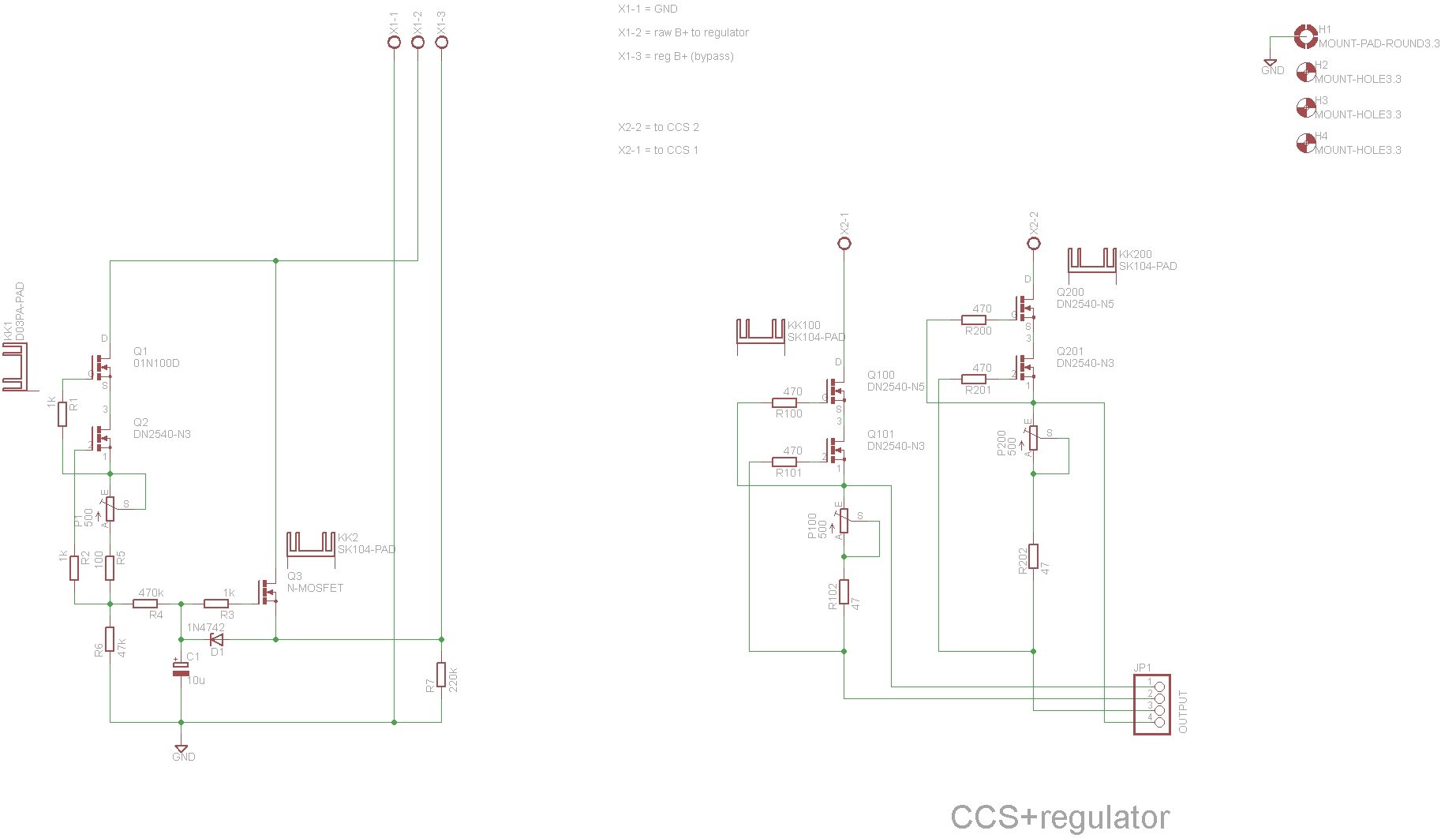
To made it clear, suggested CCS is something like this
I think the schematic from this post in the same thread is easier to adapt and all value are, more or less, there.
But there's still the bigger problem of all: space on PCB...
I can't imagine how to squeeze-in 4 TO220 FETs (and two heatsinks) and six resitors in the space of 2 TO220 and 2 resistors...

Something simpler is needed...
Attachments
Last edited:
I can't imagine how to squeeze-in 4 TO220 FETs (and two heatsinks) and six resitors in the space of 2 TO220 and 2 resistors...
Something simpler is needed...
Mmh...
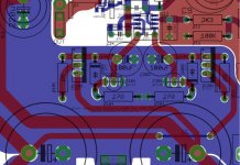
Maybe something like this dual fet could help...
Can it be suitable?
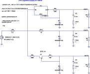
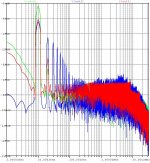
Here is the LTSpice simulation schematic (hope it uploads correctly from Opera on my phone). The 3 sections are 3-terminal regulator (LT1086-5) CCS, plain resistor CCS and JFET CCS.Siva, can you post a schematic of what you simulated? It's not clear to me...
The regulator does best on the 20 kHz ripple, but worst on the harmonics. OTOH, the plain zener does worst on the 20 kHz ripple, but best on the harmonics.
Attachments
Can anyone elaborate why a CCS would be better than the original MyRef design?
The CCS keeps the current from the main (LM3886) PSU rails constant, regardless of spikes/dips in the rail voltage caused by the LM3886. It keeps the voltage contamination on the chipamp rails from reaching the +/- 12V shunt regulator, thus improving the ripple rejection of the shunt regulator. The best CCS would be an N-ch depletion-mode TO220 MOSFET with a Vds max of at least 50V, preferably 100V.
Here is the LTSpice simulation schematic (hope it uploads correctly from Opera on my phone).
...
The regulator does best on the 20 kHz ripple, but worst on the harmonics. OTOH, the plain zener does worst on the 20 kHz ripple, but best on the harmonics.
Thanks, now it's clear.
So what you simulated is the effect of the different CCSs.
When I've added the LM317 CCS to the Zener + Transistor simple shunt made a clearly audible difference: blacker background, wider and deeper soundstage, sweeter.
It's easy to retrofit it in Rev C boards.
It keeps the voltage contamination on the chipamp rails from reaching the +/- 12V shunt regulator, thus improving the ripple rejection of the shunt regulator.
It should also avoid the inverse (contamination of LM3886 rails by the LM318 PS modulations).
Also the transistor shunt should help in this regard.
The best CCS would be an N-ch depletion-mode TO220 MOSFET with a Vds max of at least 50V, preferably 100V.
Considering the needed current (20-50mA) do you think it's possible to use only a single MOSFET instead of a cascode?
well, for this purpose you may consider the maximum possible current absorbed by the load (318+Zener or shunt reg) in the worst case and assume R=V/I.Jokes apart how can I know the minimum impedance of the attached load?
Then we have:
Xc=1/(2*Pi*f*C)
solving for C:
C=1/(2*Pi*f*Xc)
substituting Pi=3.14, f=10Hz (min operating freq) and the condition Xc<<R (say Xc<=R/10) we get:
C>=1/(6.28*R)
In practice, I guess that something >= 470u (perhaps 1000u) 50V would do just fine.
That's the same one!I think the schematic from this post in the same thread is easier
 Sorry, I thought it was clear.
 In that diagram (the one that you mention) there are TWO complete CCSs. In the picture that I posted there are also two CCSs (on the right) plus another unrelated circuit (on the left).
you only need 2 FETs and 3 Rs for each CCS. For this application heatsinks are probably not required (and perhaps not even TO220 FETs).I can't imagine how to squeeze-in 4 TO220 FETs (and two heatsinks)
Please remember me, how much current is drawn by the 318? how much by the shunt reg?
- Status
- This old topic is closed. If you want to reopen this topic, contact a moderator using the "Report Post" button.
- Home
- Amplifiers
- Chip Amps
- My_Ref Fremen Edition - need help on PCB evaluation