which when tanslated means Dancing Salsa in the Umbu?
If you're referring to my signature, quite right, it means Dancing Salsa into the Sietch.
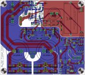
Just ordered the PCBs
After a due global check I've just ordered the PCBs from makepcb.com.
Attached is the final design gone to production.
Apart some minor cosmetic changes I've had to reverse BC640 orientation since I've discovered that Eagle default libraries have two instance of BC640, one right and one reversed...
After a due global check I've just ordered the PCBs from makepcb.com.
Attached is the final design gone to production.
Apart some minor cosmetic changes I've had to reverse BC640 orientation since I've discovered that Eagle default libraries have two instance of BC640, one right and one reversed...
Attachments
Last edited:
Dancing Salsa in the Umbu
Umbu as in Ubuntu, the Debian Linux distro ? cuz he was thanking Linuxguru ? But Ubuntu is for us beginners, he prolly uses a command-line distro like slackware.
Dario, can you give a final dimension of the boards ?
If you're referring to my signature, quite right, it means Dancing Salsa into the Sietch.
Umbu as in Ubuntu, the Debian Linux distro ? cuz he was thanking Linuxguru ? But Ubuntu is for us beginners, he prolly uses a command-line distro like slackware.
Dario, can you give a final dimension of the boards ?
Dario, can you give a final dimension of the boards ?
The PCB is 114.3 x 100.33 mm (4.5 x 3.95 inch).
I've attached the silkscreen which can be printed to have a real dimension model of the PCB.
Attachments
Can't wait to get them in here for a shootout.
Me too...
They should arrive me in the first week of February so I expect they would be in your hands by the end of February.
Currently mine sound much better than the Hafler XL280 I have on hand. There is also another amp that has regulated power supply which I have not compared with. A few more mods and I will be comparing them against some other well know amplifiers. Unfortunately I will not be able to announce any comparison against the more current products.
Some of the power supply experiences might roll back into my active speaker.
Some of the power supply experiences might roll back into my active speaker.
Last edited:
the current pump requires very accurate selection of resistor values to enable the pump to work correctly.
It also appears that the error on either side of true and exact matching gives different results. A -ve resistor match is not the same as a +ve resistor match.
I matched my resistors off board, but being aware of the -ve match condition being possible I then did an on board match taking account of trace and solder resistances. I had to do a final on board trimming to correct for the on board resistances. I erred very slightly towards the +ve resistor match, so that when temperature effects came in I did not get my carefully set up +ve ratio swapping over to a -ve ratio.
Having done all that work I was not inclined to try altering the ratios to investigate the differences between big+ve, little +ve, zero, little -ve, big -ve.
Has anyone managed to hear or measure any differences when the pump resistor matching is varied?
the current pump requires very accurate selection of resistor values to enable the pump to work correctly.
So you think that Mauro's specs of 0.1% is not enough?
Can you tell us what to expect from a better matching?
I matched my resistors off board, but being aware of the -ve match condition being possible I then did an on board match taking account of trace and solder resistances.
1cm of 70mils 2oz PCB trace should measure 0.00137 Ohm...
The 0.01% of the smaller resistor (22K) is 220 Ohm
Am I right?
I don't understand...how much precision are you trying to reach?
Has anyone managed to hear or measure any differences when the pump resistor matching is varied?
No Andrew, I never experimented on that. Sorry.
From the information available, it seems involved with stability. I think the 0.1% is insane enough to bear with. The voltage feedback does have some effect on damping. The value I mentioned in the other thread seems to sound cleaner, when measured, it also had some improvement in damping, not by too much though.
Last edited:
0.1% precision is not the issue.
Look up the original threads and the Howland current pump and you will find it is the ratio being very close to 1:1 that is important.
The length of the exposed lead affects the resistance substantially when working at the 0.1% or 0.05% matching level.
If you look back you will find that I advised doing the on board matching before adding in other components. I remember asking whether we could partially populate the PCB and still get effective matching on board.
The subtlety behind my question appears to have gone straight past most readers.
This was intended to find if it was possible for others with assembled PCB to revisit the matched tolerance simply by removing the 318 from the socket.
Last edited:
Has anyone managed to hear or measure any differences when the pump resistor matching is varied?
The subtlety behind my question appears to have gone straight past most readers.
This was intended to find if it was possible for others with assembled PCB to revisit the matched tolerance simply by removing the 318 from the socket.
sorry i failed to see any subtle implication in your question. if you're simply asking whether the desired matching can be regained by removing the op-amp, you should have asked so (to which my answer would've been 'I don't know') because wishful intent and direct communication are two different things.
Don't be sorry. You haven't done anything you need to apologise for.sorry i failed to see any subtle implication in your question.
I am not sure how long ago I asked, you may not have been a Member then.
the current pump requires very accurate selection of resistor values to enable the pump to work correctly.
It also appears that the error on either side of true and exact matching gives different results. A -ve resistor match is not the same as a +ve resistor match.
0.1% precision is not the issue.
Look up the original threads and the Howland current pump and you will find it is the ratio being very close to 1:1 that is important.
Hi Andrew,
is this the post you're referring to?
http://www.diyaudio.com/forums/chip-amps/167458-myrefc-build-guide-4.html#post2214408
I'm not sure I understand what it means a +ve matching...maybe that the voltage difference is positive?
The length of the exposed lead affects the resistance substantially when working at the 0.1% or 0.05% matching level.
Shouldn't the use of smd components address, at least in part, this problem?
While searching for your posts on this argument I've also found another interesting post about Siva's 1.3 PCB:
http://www.diyaudio.com/forums/chip-amps/134726-new-my-ref-rev-c-thread-21.html#post2249909
Sadly I've missed it... it's a pity that you didn't pointed it also in this thread
It would have been interesting trying to implement it with ground planes
An interesting Application Note from National on what Andrew is talking about:
http://webench.national.com/an/AN/AN-1515.pdf
http://webench.national.com/an/AN/AN-1515.pdf
Perhaps the board can be designed so that on board matching is not required?0.1% precision is not the issue.
Look up the original threads and the Howland current pump and you will find it is the ratio being very close to 1:1 that is important.
The length of the exposed lead affects the resistance substantially when working at the 0.1% or 0.05% matching level.
If you look back you will find that I advised doing the on board matching before adding in other components. I remember asking whether we could partially populate the PCB and still get effective matching on board.
The subtlety behind my question appears to have gone straight past most readers.
This was intended to find if it was possible for others with assembled PCB to revisit the matched tolerance simply by removing the 318 from the socket.
Clave,
is there any point in me trying to offer you advice?
All I can do is offer build advice to those who follow you. Some Members may be open minded enough to take on board both sides of the discussion and then decide which direction to go.
Many Members on this Forum see me as an interfering old codger and as a result give little if any weight to my warnings/advice/recommendations.
You have to decide if you want to listen to my ramblings, or do as others and add me to their ignore list.
SMD may help since it potentially offers shorter trace lengths. But adopting SMD alone does nothing to improve on board tolerances of matching.
I try to help. I have no other agenda.
BTW,
all the links are pointing to relevant information.
Last edited:
I doubt it. But very careful layout where a true bridge with equal impedance sides could maybe just be laid out.Perhaps the board can be designed so that on board matching is not required?
- Status
- This old topic is closed. If you want to reopen this topic, contact a moderator using the "Report Post" button.
- Home
- Amplifiers
- Chip Amps
- My_Ref Fremen Edition - need help on PCB evaluation