We are not considering the connector only, we are considering the current path and it's distance/orientation.
I've tried a different arrangement but I'm not satisfied, too much obstacles to the return current... any idea?
I am also having some second thoughts on the LM3886 ground. If the board comes connecting pin 7 to power ground, it becomes difficult to change it back to the original MyRef.
It's possible to make a solder jumper (see attachment) that makes possible grounding choice, I'll give it a try but all that I've read, the Evolution Rev A, listened and my instinct brings me to PGND... can you elaborate?
Attachments
Last edited:
Since this is a prototype, I'd like the flexibility to explore various options. If I had more RefC boards, I could also use those. But the final decision for me is match between measurements AND listening. Not just listening alone.I've tried a different arrangement but I'm not satisfied, too much obstacles to the return current... any idea?
It's possible to make a solder jumper (see attachment) that makes possible grounding choice, I'll give it a try but all that I've read, the Evolution Rev A, listened and my instinct brings me to PGND... can you elaborate?
Since this is a prototype, I'd like the flexibility to explore various options. If I had more RefC boards, I could also use those.
In fact it's also possible to use both grounding schemes in the same way we do it with TP boards... lifting pin 7 and connecting it to PGND or 0V...
I'm not sure including a solder jumper it's the best option, it would be nice if other partecipants give feedback about it...
But the final decision for me is match between measurements AND listening. Not just listening alone.
So you just want to listen and measure to both grounding schemes?
I've thought you had some doubts for something else...
Prototyping means to me flexibility to try out different configurations. Preproduction means doing a selected configuration. But I could also just cut the trace myself.
I'm not excluding the solder jumper, just want to know what others thinks about it.
")
I've found a few SPICE models out there looks like I'm going to have to do sims myself.
We'll wait for your sims
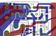
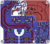
In the meanwhile I've mananged to find, reverting to G5LE, a layout with a good distance between input cap and output ground connector.
Since no one wrote nothing about it I've also inserted the solder jumper but I'm still doubtful about it.
I fear that in this way the separation between 0V and GND could suffer... any opinion on it?
Attachments
Last edited:
I have quite a few things on hand, I was hoping someone else could work on that part.
I would have done it but I don't have the necessary knowledge and in this moment I'm too busy to acquire it...
For the ground, as long as the current paths are not too much in parallel, ig should be okay. Hard to se on my phone.
I don't know if doing much better is possible but I'm confident we have a good layout now.
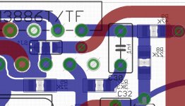
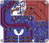
I've done some further mods:
- 12mm lead spacing for through-hole resistors
- modified a bit more the DC protection layout.
BTW from my LG Optimus One I can see it quite good
Attachments
Last edited:
On the toilet of a MacDonalds is not the best place to try and figure things out. But one thing I remembered while trying to use a different C13 is that the hole was too small for many of the Caps I have on hand, including Mundorf Silver/Gold. What have you looked into it?
On the toilet of a MacDonalds is not the best place to try and figure things out.
But one thing I remembered while trying to use a different C13 is that the hole was too small for many of the Caps I have on hand, including Mundorf Silver/Gold. What have you looked into it?
I've used a library which is specific for Mundorf Zns and I can confirm that the hole is bigger (50mils Vs 40mils).
are you specifying Plated Through Holes (PTH)?
Check with the manufacturer on the tolerance of plating thickness to determine the finished minimum diameter of PTH holes.
Check also the tolerance of plating and roundness of leadout wire for the through hole devices. You as PCB designer must check the maximum diameter of the lead out and the minimum diameter of the hole.
50mil PTH may not allow a 40mil plated wire to pass through.
are you specifying Plated Through Holes (PTH)?
Check with the manufacturer on the tolerance of plating thickness to determine the finished minimum diameter of PTH holes.
Check also the tolerance of plating and roundness of leadout wire for the through hole devices. You as PCB designer must check the maximum diameter of the lead out and the minimum diameter of the hole.
50mil PTH may not allow a 40mil plated wire to pass through.
Hi Andrew,
thanks for the info, I'll check.
I've checked on PCB manifacturers web sites and found nothing about plating tolerances, sadly.
But I can say for sure that in TP boards in C13 1.0 mm Mundorf Zns wires fits, tightly, but fits in 1.0mm holes.
The holes in Zns library I'm using are 1.27mm so they would accomodate easily 1.0mm wires but not 1.4mm of Mundorf Silver/Gold.
Is this a problem?
Mundorf SG wires could be slightly filed and they'll fit, anyway.
Not my TP boards. Most of the caps of mine won't go through, and if we are going to try out different caps, we need to be able to remove multiple times where residual solder is going to fill the hole a bit. I've already had the throughholes come out on my R3's. Maybe the 1.27mm is okay to try since these are prototypes.....
But I can say for sure that in TP boards in C13 1.0 mm Mundorf Zns wires fits, tightly, but fits in 1.0mm holes.
...
I am using lead free solder. Probably the normal lead solder works better.
Not my TP boards. Most of the caps of mine won't go through, and if we are going to try out different caps, we need to be able to remove multiple times where residual solder is going to fill the hole a bit. I've already had the throughholes come out on my R3's. Maybe the 1.27mm is okay to try since these are prototypes.
I am using lead free solder. Probably the normal lead solder works better.
I think you're right pointing out the lead free solder...
When TP boards were new the Zns leads mounted quite easily, after desoldering they don't fit unless you put some new solder in the empty hole and suck it with a vacuum pump.
Only after I've buyed a desoldering station I've managed to have those pads really clear...
Obviously I've always used leaded solder.
On the MINI2496 I've used lead-free solder and the only way to have a clean pad after desoldering is to wet the void hole with leaded solder...
I'm confident that the 1.27mm holes will help us with 1.0mm leads.
I have your mini2496 BOM pdf , great work. I am considering buying this to be my first DAC build. Do you also have a BOM for Mesmerize DCB1 ?On the MINI2496 I've used lead-free
For those of us who do not want to use C13 could you add a thru hole closer so we can use a smaller jumper , maybe have a line printed to it on the silk?
Last edited:
I have your mini2496 BOM pdf , great work. I am considering buying this to be my first DAC build. Do you also have a BOM for Mesmerize DCB1 ?
Thanks
I do have a Mezmerize but not an optimized BOM for it, I've simply built it with good quality parts (PRP, Riken, Blackgate, Nichicons).
Maybe next year I'll optimize it.
For those of us who do not want to use C13 could you add a thru hole closer so we can use a smaller jumper , maybe have a line printed to it on the silk?
In the first version pads for 22 and 15mm caps were present but I've removed it since the supporting trace would have changed the impedance of the input trace.
Anyway if you're using (or planning to) the Mezmerize you'll need an input cap for the MyRef.
- Status
- This old topic is closed. If you want to reopen this topic, contact a moderator using the "Report Post" button.
- Home
- Amplifiers
- Chip Amps
- My_Ref Fremen Edition - need help on PCB evaluation