At the risk of sounding super silly - since the boards will be sold and used in pairs, would there be an advantage/possibility to create "mirrored pairs" for the sake of consistency in internal wiring and board placement options. Don't know if this has ever been done but I have seen it used on 2 channel single boards designs.
The problem with "mirrored pairs" is that internal wiring cannot be consistent since (if nothing else) the LM3886 pins have to be in the same order and cannot be mirrored.
-b
Whatever you decide, I'll just get a set and figure out what to do with it when I get it. Still need to run some additional tests anyway. This design seems really sensitive to layout. With the last layout, I still think the OUT trace is too close to the limiters. Have not checked the two ground currents yet.Sorry, I can't understand well...
I don't know if the PCB factory ships individually but I don't think so. Not without a surcharge.
In every GB, from what I know, there's a single person who receive all PCBs and then package and ships them individually.
Making some PCBs with HASL and some with Chemical Gold would increase cost since the price goes lower with higher numbers...
BTW this sort of things should be discussed while organizing the GB, in this moment we're only trying to prototype the amp...")
Last edited:
Maybe now you can REALLY redesign....
I've upgraded to Eagle 6.0 and it was a great mistake!
Eagle 6 have several problems (some serious) and the 0.9.7 version is now only Eagle 6 compatible so I'll have to redesign it in Eagle 5, it will take a day or two more...
wrankin,
Good point. It probably could be done but with a lot of redesigning and most likely not that much of an advantage compared to the effort required.
If someone (not Darly - his plate is full) has the software, time and inclination, it would be fun to see a single board two channel design with the features of the MyRef.
But, that's a future new thread and off topic here. 'Nuff Said
The problem with "mirrored pairs" is that internal wiring cannot be consistent since (if nothing else) the LM3886 pins have to be in the same order and cannot be mirrored.
Right! I've thought about it just after my last post...
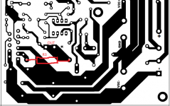
Whatever you decide, I'll just get a set and figure out what to do with it when I get it. Still need to run some additional tests anyway. This design seems really sensitive to layout. With the last layout, I still think the OUT trace is too close to the limiters. Have not checked the two ground currents yet.
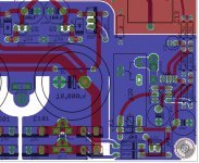
Yes, the design is sensitive to layout, in fact Mauro always stated that his PCB was integral part of it...
Regarding the OUT trace is probably hard to do much better...
See the attached magnification of Mauro's design.
Maybe now you can REALLY redesign.
Not completely, as last time I'll start from 0.9.6...
Do you think a COMPLETE redesign is needed?
One thing I was thinking is how to ground the chassis. It's probably acting like a passive device right now.
The basic way is PGND to chassis, chassis to safety heart (what I'm using).
More advanced techniques include a 'ground breaker' or similar.
Attachments
Last edited:
makepcb is much cheaper... 67€ for 6 boards excluding shipping (31€ via express courier or 13€ via air mail).
So if I got two boards it would lower the cost for you three ? For less than $40.00 usd ? I want please. I thought there would be more people interested by now.
So if I got two boards it would lower the cost for you three ? For less than $40.00 usd ? I want please.
Yes, if you join the cost for all will be lower (26€/34US$ + shipping)
So in your case it would be 34+16=50US$ at the actual (low) exchange rate Euro/Dollar.
To keep price low for beta testers I'm carrying import duties from China (ca 14€) but if a fifth member will join I'll order from Italy or I'll split import duties among members.
I thought there would be more people interested by now.
I'm sure a lot of people is interested in a possible GB for tested (and cheaper) PCBs but in this moment they don't want to carry the risk of an untested board.
I think it's quite normal...
Last edited:
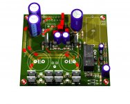
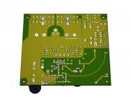
Final (?) PCB
I've managed to redesign the PCB for Eagle 5 and while doing it I've made some changes:
I've managed to redesign the PCB for Eagle 5 and while doing it I've made some changes:
- the only SMD components are in the amp section
- changed output relay to Omron G2R
- looks great...
Attachments
I find it annoying to have signal ground of MyRef connected to power ground of other equipment.The basic way is PGND to chassis, chassis to safety heart (what I'm using).
More advanced techniques include a 'ground breaker' or similar.
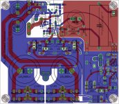
Are you sure you want the speaker ground so close to the input?
I've rearreanged things a bit, now distance is bigger, see attachment.
Thanks
I find it annoying to have signal ground of MyRef connected to power ground of other equipment.
PGND is insulated from signal ground by R11...
Attachments
The distance still seems smaller than the original MyRef though.I've rearreanged things a bit, now distance is bigger, see attachment.
Thanks
PGND is insulated from signal ground by R11...
The input ground is the signal ground, but this input ground is connected to the power ground of the other device which is the ground of the RCA connector.
The distance still seems smaller than the original MyRef though.
You're right. Distance if half Vs TP boards.
This night I'll try to get some more distance but I'm not sure how much more is possibile to gain.
BTW, PCB wise, the output ground is still PGND, so the entire ground-plane can, potentially, irradiate.
Even if the connector was near the two SBY27 current return toward the 'starground' between the two smoothing capacitors, so passes near the actual position of OGND, isn't it?
Can you explain why the position of the OGND connector is so important and why it differs from the same potential PGND ground-plane?
The input ground is the signal ground
Sure
but this input ground is connected to the power ground of the other device which is the ground of the RCA connector.
Here I've lost you...
how can you say another device has signal ground connected to power ground, it can be or not.
But, most of all, if the other device is designed in that way what can you do about it on the amp?
The ground in circuits may not be ground as we know it, in case of the MyRef, it certainly is not. Ground is used as a reference point for all circuit analysis mainly for convenience. If you read Bill Whitlock's AES tutorial on grounding, it presents how to avoid grounding problems. With the MyRef, its input ground connection is connected to the signal ground, however, in most cases, this ground connection is the ground for the device, thus interacts with the other devices it is connected to in an unpredictable way. This is not an ideal situation. Just my point of view. I am still trying to think about how to solve it. But don't hold your breath on it.You're right. Distance if half Vs TP boards.
This night I'll try to get some more distance but I'm not sure how much more is possibile to gain.
BTW, PCB wise, the output ground is still PGND, so the entire ground-plane can, potentially, irradiate.
Even if the connector was near the two SBY27 current return toward the 'starground' between the two smoothing capacitors, so passes near the actual position of OGND, isn't it?
Can you explain why the position of the OGND connector is so important and why it differs from the same potential PGND ground-plane?
Sure
Here I've lost you...
how can you say another device has signal ground connected to power ground, it can be or not.
But, most of all, if the other device is designed in that way what can you do about it on the amp?
When you driver speakers, you basically have current flowing though it's path, so it will have an alternating magnetic field which in turn induces current in conductive devices near by. If you have any of the speaker driving paths close to the input or any part of the small signal devices, this induced signal will interact with the input throughout the circuit.
I hope to post tomorrow a very preliminary BOM (just to make an idea of costs).
You'll find attached the preliminary BOM.
For a full compliant order at least two suppliers must be used (Mouser and Parts Connexion):
Mouser 52.75$/monoblock
PCX 79.54$/monoblock
It should be taken in account that in PCX order 55.72$ are for the Mundorf AGs.
If you make a full 'industrial' choice with a full order from Mouser apart the Mundorf Zn (18.32$) it will cost 73.67$/monoblock
My suggestion if you want to save some money is to buy all PCX parts except Mundorf AGs.
But for a full experience (the difference between TS-HAs and AGs is not small, IMHO) the full BOM should be buyed.
Elna RJHs must be ordered from Elfa.se or eBay, if you can find an US supplier please let me know.
Attachments
Last edited:
With the MyRef, its input ground connection is connected to the signal ground, however, in most cases, this ground connection is the ground for the device, thus interacts with the other devices it is connected to in an unpredictable way. This is not an ideal situation. Just my point of view. I am still trying to think about how to solve it. But don't hold your breath on it.
I do agree but it's not a fault of the amp design
If you find a simple solution for that problem it will be included, obviously.
When you driver speakers, you basically have current flowing though it's path, so it will have an alternating magnetic field which in turn induces current in conductive devices near by. If you have any of the speaker driving paths close to the input or any part of the small signal devices, this induced signal will interact with the input throughout the circuit.
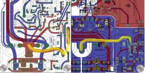
I know, what I'm missing is why the connector should be treated differently from the ground plane.
They're at the same potential and the connector goes, via the relay, to ground-plane.
See the attachment for a comparison between TP and FE return current paths
But obviously I'll try to gain distance, yesterday I had no time since I was preparing the BOM.
Attachments
We are not considering the connector only, we are considering the current path and it's distance/orientation.I do agree but it's not a fault of the amp design
If you find a simple solution for that problem it will be included, obviously.
I know, what I'm missing is why the connector should be treated differently from the ground plane.
They're at the same potential and the connector goes, via the relay, to ground-plane.
See the attachment for a comparison between TP and FE return current paths
But obviously I'll try to gain distance, yesterday I had no time since I was preparing the BOM.
I am also having some second thoughts on the LM3886 ground. If the board comes connecting pin 7 to power ground, it becomes difficult to change it back to the original MyRef.
Last edited:
We are not considering the connector only, we are considering the current path and it's distance/orientation.
I've tried a different arrangement but I'm not satisfied, too much obstacles to the return current... see the attachment... any idea?
I am also having some second thoughts on the LM3886 ground. If the board comes connecting pin 7 to power ground, it becomes difficult to change it back to the original MyRef.
It's possible to make a solder jumper that makes possible grounding choice, I'll give it a try but all that I've read, the Evolution Rev A and my instinct brings me to PGND... can you elaborate?
- Status
- This old topic is closed. If you want to reopen this topic, contact a moderator using the "Report Post" button.
- Home
- Amplifiers
- Chip Amps
- My_Ref Fremen Edition - need help on PCB evaluation