Mauro chose not to detail any of the evolution to DIYaudio Members.
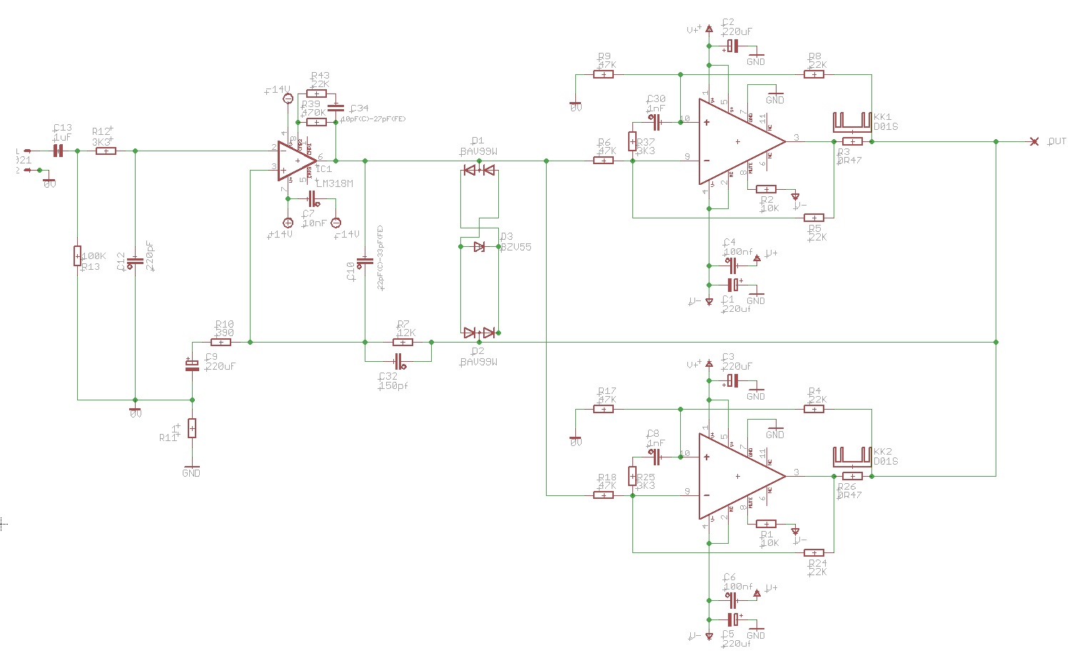
An Italian Audio magazine published (with Mauro's permission) a schematic of the Evolution with most of the values of the passives omitted. The DC Servo topology was shown. With some knowledge of the MyRef and general amplifier design, it is possible to deduce the approximate values of all the passives. At any rate, the DC Servo is not critically dependent on the exact values of the passives, and will work with generic values obtained from independent analysis/simulation.
The DC Servo in the Evolution injected the correction signal into the input node, rather than the feedback node. Both topologies are feasible, but the latter is simpler to analyse.
Last edited:
Ask Mauro for permission and then post data.
Actually, the copyright belongs to the magazine, but fair-use exemptions should allow a small excerpt to be posted here with attribution (without violating copyright). That can, for instance, be the image of the schematic that was published.
Well here is another (extreme) possibility that hopefully would not violate any legal and/or personal agreements. It has been reported that the early developments for the MyRef were based on the TDA7294, and also that a large portion of the MyRef sonic signature is due to the LM318. Since several of you with expert knowledge are gathering in a cooperative spirit in this effort, could this be an opportunity to investigate (return to) where Mauro began - and develop something new from there. That might remove the copyright challenges and even present options and/or alternatives to the LM318 impact of a new high quality power amp.
It's an idea I presented earlier but have not participated in strongly due to the time spent with my adventures in discretes. Others have continued so some information is available on that thread. It's a real departure from the long and valued history of the MyRef/Lm3886 but may be worth consideration. I don't have the knowledge and background to make that determination but reintroduce the concept as an alternate direction.
All or any comments are encouraged and welcomed.")
Optimizing TDA7294 Output
It's an idea I presented earlier but have not participated in strongly due to the time spent with my adventures in discretes. Others have continued so some information is available on that thread. It's a real departure from the long and valued history of the MyRef/Lm3886 but may be worth consideration. I don't have the knowledge and background to make that determination but reintroduce the concept as an alternate direction.
All or any comments are encouraged and welcomed.
Optimizing TDA7294 Output
Last edited:
there are many badly designed or badly assembled chipamp power amplifiers, where the builder/designer forgets that +-2mVdc is an achievable offset target without any special procedures.
Absolutely, Andrew, as I wrote the next paragraph....
BTW we want less than 10mV so C9 or a DC-Servo are still needed.
Andrew, will you answer my questions to your notes?
I think it would be an interesting read.
I wonder if it is possible to publish here just the scheme. Dario, what do you think? It may help a lot.
Hi Daniele,
I have that scheme but I don't think it's a great idea to post it without Mauro's permission
That could well be. Maybe he found empirically for LM318 (with the parts he had) that unbalancing source resistances leads to some cancelling of offset contributing mechanisms, that is, cancelling a systematic voltage offset with a proper selection of current-induced offset and by lucky chance it happened to be that the DC resistance at the -IN needs to be higher for this than at the +IN (well, maybe it just happened this way, he consistently saw little offset, then let's keep it this way in spite of the imbalance he was surely aware of).
In my mail exchange with Mauro during the FE design phase he insisted on the nets around the LM318, including the input cap to ensure the proper biasing of the LM318 according to his design goals.
This could be a hint that you're on the right path.
It has been reported that the early developments for the MyRef were based on the TDA7294, and also that a large portion of the MyRef sonic signature is due to the LM318. Since several of you with expert knowledge are gathering in a cooperative spirit in this effort, could this be an opportunity to investigate (return to) where Mauro began - and develop something new from there.
Bob,
Mauro abandoned TDAs in favour of LM3886 because the formers where not giving the results he pursued.
IMHO it would/could be a drawback.
Bob,Mauro abandoned TDAs in favour of LM3886 because the formers where not giving the results he pursued. IMHO it would/could be a drawback.
That's fine, just thought I'd throw it out there.
http://www.diyaudio.com/forums/attachment.php?postid=673432&stamp=1120201026
http://www.diyaudio.com/forums/attachments/solid-state/69634d1157061661-mf-370-mf-a370.pdf
The input stage and NFB are borrowed from the MF A 370. Looks like the My_ref is missing a 10k resistor at the input.
http://www.diyaudio.com/forums/attachments/solid-state/69634d1157061661-mf-370-mf-a370.pdf
The input stage and NFB are borrowed from the MF A 370. Looks like the My_ref is missing a 10k resistor at the input.
Last edited:
In my mail exchange with Mauro during the FE design phase he insisted on the nets around the LM318, including the input cap to ensure the proper biasing of the LM318 according to his design goals.
This could be a hint that you're on the right path.
That is an interesting puzzle. As I have said before, Mauro is a creative and expert designer who has often found unusual and unconventional solutions. Maybe this is one.
Intentionally having unequal input impedances at the +/- input of the 318 almost ensures some kind of DC bias. Anybody have any clue how that could be useful? Could it be a little like Class A bias with the offset reducing crossover distortion? I admit to be totally guessing here. It doesn't make any sense to me.
I am also curious because it seems that Mauro kept very similar network schemes on the Evolution, but replaced the C9 gain reduction scheme with the DC servo to control DC offset. That would seem to imply that some level of DC bias was not what he was trying to achieve, but that the values he chose were for other reasons.
I understand and respect his reasons for withdrawing from the forum, but I wish he were here to explain. We could learn a lot from him.
Jac
http://www.diyaudio.com/forums/attachment.php?postid=673432&stamp=1120201026
The input stage and NFB are borrowed from the MF A 370. Looks like the My_ref is missing a 10k resistor at the input.
Very interesting circuit! Yes, the MyRef borrows heavily from this topology, but the compensation differs considerably. There's an RC dominant pole between the offset trim terminals of the LM318 (collector-to-collector on the LTP), which will have the effect of limiting the BW of the opamp. That's quite heavy-handed actually, at 3k3 || 2n2 (the Rev C uses 3k3 || 1n at the input of the LM3886 - which appears to have been borrowed from here).
There's a second 5pF from output to comp - a bit lower than the 10pF-22k of the Rev C.
I don't quite understand what to make of the 10k at the input - it's connected to the feedback node, so it presents a bootstrapped impedance to the input (much higher than 10k).
The LM318 output stage is operating in Class-B! Look carefully at the biasing of the cascode drivers - both bases are at ground potential. However, given the slew-rate of the LM318, this may not be a problem.
Some effort has been invested in asymmetric gate-drive turn-off capacitors - the values are probably closely tied to the specific MOSFET pairs used.
(This whole LM318+cascode+MOS block could be usefully evaluated as a high-power discrete chipamp replacement also - I'll look at it in simulation later).
the copyright of the published no values sch belongs to the publisher.Actually, the copyright belongs to the magazine, but fair-use exemptions should allow a small excerpt to be posted here with attribution (without violating copyright). That can, for instance, be the image of the schematic that was published.
You need their permission to use their sch.
If you want to post a full sch you need Mauro's permission.
DIYaudio have severe penalties, if they wish to use them, for posting copyright protected and IP without permission.
They even have penalties for posting links to sites that have unauthorised or infringements to copyright and/or IP buried elsewhere in their sites.
What questions, what notes?..........Andrew, will you answer my questions to your notes?..............
Well, it adds a tiny bit of noise gain...not the reason why it is there. In fact it is the DC input resistance balancing resistor to equal bias current offsets as discussed, (10k+3k3+560R) vs 12k, that gets bootstrapped for AC as you say, plus giving the whole thing a stronger LF rolloff. Obviously a more clever way to do that than simply reducing the 100k like I suggested. The more obscure it is why Mauro choose to remove it....I don't quite understand what to make of the 10k at the input - it's connected to the feedback node, so it presents a bootstrapped impedance to the input (much higher than 10k).
An idea for beefing up output power of the myRef just occured to me : it looks quite feasible to paralles a second LM3886 current pump and use slightly higher supplies. With the V to I transfer reduced to 1/2 of the original value for each section the overall conditions for the LM318 would be the same. One would need to alter the Zener overdrive clamp. That is one the secrets of the myRef topology with the frontend running inverted (not: inverting). Some care would needed to check for / avoid cross currents, actually one could even establish some cross-current on purpose to bias the output stages to more of class-A operation at low output current levels, de-symmetrizing the crossover to below and above zero current for each half.
What questions, what notes?
Your post:
http://www.diyaudio.com/forums/chip...ollaborative-dc-servo-design.html#post3952536
Questions:
http://www.diyaudio.com/forums/chip...ollaborative-dc-servo-design.html#post3953000
What I find most interesting (difficult to understand) is the placing of a current pump within a voltage gain loop. The NFB loop must be compensating (removing) the V to I transfer. It does give the LM3886 a nice balanced input though.
http://www.diyaudio.com/forums/attachments/chip-amps/54486d1133860004-x-calibre-hot-rodding-mauro-penasas-lm3886-design-x-comp.pdf
Paralleled My_ref.
http://www.diyaudio.com/forums/attachments/chip-amps/54486d1133860004-x-calibre-hot-rodding-mauro-penasas-lm3886-design-x-comp.pdf
Paralleled My_ref.
The whole idea behind the myRef is to have the frontend see the speaker current, the output of the LM318 is a replica of it and the feedback servos this output -- the control voltage for the LM3886 -- to what's needed to establish the proper output voltage.
There is good reason to assume this is more benign sounding than if the LM3886 were just a power buffer with gain.
Hm, I cannot see a second power stage on the board you linked to.
There is good reason to assume this is more benign sounding than if the LM3886 were just a power buffer with gain.
Hm, I cannot see a second power stage on the board you linked to.
Parallel current pump
On the original My_Ref thread it was already proposed a double pump approach:
http://www.diyaudio.com/forums/chip-amps/54571-my-audiophile-lm3886-approach-54.html#post1139692
You'll find Lukio's schematic there; his use of the current pumps is identical to My_Evo (Evolution) one.
This is the version I've did some time ago while exploring the concept, probably identical to Siva's one:
there's no a version I'm aware of where the voltage rails are higher than My_Ref's ones.
Attachments
Last edited:

the opamp output VOLTAGE with respect to audio ground is divided by R5/Ri. the correction VOLTAGE at -IN is Ri / [Ri+R5]......Why should R10 be used instead of R7 (which is the feedback resistor of the composite amp, right?)?
The gain of the amplifier is Rupper/Rlower + 1
Rlower is modified when the DC servo is added.
Rlower effectively becomes 1k||205k = 0k995 Close enough to 1
If one makes the injection resistor ten times Rlower then adopting 1k1 and 11k gives an effective Rlower of 1k, close enough that the amplifier gain is still the same.
using the above VOLTAGE equation and assuming +-15Vdc supply rails to the opamp, the maximum output voltage will be ~14V with respect to audio ground. The maximum correction voltage will be ~14*1k/[205+1] =~68mVdc.I've simply followed AN-1192:
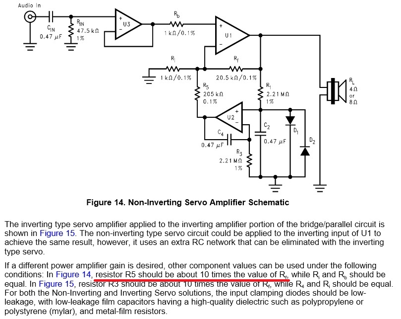
(excerpt from TI AN-1192)
Can you, please, elaborate?
Note that I am NOT using currents as some other Members have used in referring to the correction signal.
When the amplifier gain is used, one ends up with a maximum correctable output offset of ~30times 68mV = ~2Vdc That is quite a small range.
the output of the opamp is contaminated with noise and distortion. Once this is injected into -IN, it cannot be attenuated, nor can it be removed. A filter to attenuate before injection seems to me better at making the DC servo inaudible.............with a so low Fc (0.16Hz) how much AC would pass past the DC Servo? Isn't filtered enough?
But, D.Self (I read the chapter just yesterday) says adding a second pole is risky. It needs to be designed in, to avoid adding stability problems.
Going as low as 0.16Hz makes the DC servo relatively slow. What about 1Hz, or 2Hz, or 0.5Hz?
Last edited:
First of all, Andrew, thanks for the very informative post
So, if I understood correctly, we should not only evaluate the R12 Vs RSO1 but also the RSO1 Vs R10 ratio to ensure that amplifier gain remain almost the same, also the RSO1 Vs R10 determine the pull range and 10x give a not so big headroom, right?
Nevertheless according Klaus' calculations we should need a much lower (less than 160mV) than 2V range, correct?
Absolutely but shouldn't a very low Fc do the same?
Yes, same thing Cordell wrote on the excerpt I've posted.
It's for this reason, along with the possible audibility of the filter cap, that I would prefer to address the problem in a simpler to design way.
It was simpy the AN-1192 value and I kept it as it was.
If I understood correctly a slow servo is not a bad thing since it should avoid that the servo try to 'correct' the signal instead of the DC offset, isn't it?
Nevertheless a higher Fc would allow a smaller value cap... how can we determine when it's slow (or fast) enough?
the opamp output VOLTAGE with respect to audio ground is divided by R5/Ri.
(...)
When the amplifier gain is used, one ends up with a maximum correctable output offset of ~30times 68mV = ~2Vdc That is quite a small range.
So, if I understood correctly, we should not only evaluate the R12 Vs RSO1 but also the RSO1 Vs R10 ratio to ensure that amplifier gain remain almost the same, also the RSO1 Vs R10 determine the pull range and 10x give a not so big headroom, right?
Nevertheless according Klaus' calculations we should need a much lower (less than 160mV) than 2V range, correct?
A filter to attenuate before injection seems to me better at making the DC servo inaudible.
Absolutely but shouldn't a very low Fc do the same?
But, D.Self (I read the chapter just yesterday) says adding a second pole is risky. It needs to be designed in, to avoid adding stability problems.
Yes, same thing Cordell wrote on the excerpt I've posted.
It's for this reason, along with the possible audibility of the filter cap, that I would prefer to address the problem in a simpler to design way.
Going as low as 0.16Hz makes the DC servo relatively slow. What about 1Hz, or 2Hz, or 0.5Hz?
It was simpy the AN-1192 value and I kept it as it was.
If I understood correctly a slow servo is not a bad thing since it should avoid that the servo try to 'correct' the signal instead of the DC offset, isn't it?
Nevertheless a higher Fc would allow a smaller value cap... how can we determine when it's slow (or fast) enough?
Pull range
From a previous thread I started on a replacement opamp for My_Evo's DC -Servo:
Any though on it?
From a previous thread I started on a replacement opamp for My_Evo's DC -Servo:
The real concern is however is if the Servo is implemented to minimise it's pull range to what is needed.
I recently came across a design which had a 100K feedback resistor and a 22k resistor from the servo into the feedback node. The Servo was a 072 running on 15V rails, the offset it actually corrected caused less than 0.1V to appear on the Servo Op-Amp output.
So the servo was injecting whatever it did into the feedback node with five times as much gain as the actual signal and it was doing so unnecessarily.
Using a 1M resistor to feed in the servo output caused much more voltage on the servo, but no more actual DC output from the circuit, meanwhile the noise, distortion etc. from the servo entering the signal path was reduced by 34dB!
Any though on it?
- Status
- This old topic is closed. If you want to reopen this topic, contact a moderator using the "Report Post" button.
- Home
- Amplifiers
- Chip Amps
- My_Ref Fremen Edition - Collaborative DC-Servo design