I would go with a gyrator loaded pentode, as a V/I converter.
Wonder if that will work IRL? Maybe I missed something. The bigger Rgen(in which Ra and Rí is parallelled) is, the lower the gain. So with Ra and Ri going towards infinity, gain will diminish.
"Have you really done the maths?"
Ehhh, no. But looking at the 6AU6 curves, a .7K load sure would be making distortion in the input pentode. The feedback is linearizing the output stage and killing the input stage by loading. At least 100K needed for R12, even more would be better.
With the Gyrator type loads, they should actually free up a little extra current from the V to I input pentode for driving the feedback loading. No current waisted in the 14K Ra load. But not nearly enough fix-up to clean up the 6AU6 non-linearity problem. The cathode resistor may need increasing to 250 Ohms or more, which will require a cap on the input for biasing then. A higher gm tube than the 6AU6 would be helpful here.
Oooops, wrong maths by me . Had the wrong OPT impedance in my spreadsheet, higher OPT primary impedance means lower Rin. My figures where for 5k OPT.
Rin=2,5k with 41k, Rout=0,4k, OPT=1,5kSE
Rin=6k with 100k, Rout=0,8k, OPT=1,5kSE
Rin=4k with 100k, Rout=0,8k, OPT=2,5kSE
But the 14k Ra is needed as it is part of the feedback, as I see it, just a CCS wont work.
Of the tubes I tried, EL86/PL84 seems to be a great tube for Schadeing with its comparably high Rin and low Rout.
. Had the wrong OPT impedance in my spreadsheet, higher OPT primary impedance means lower Rin. My figures where for 5k OPT.Rin=2,5k with 41k, Rout=0,4k, OPT=1,5kSE
Rin=6k with 100k, Rout=0,8k, OPT=1,5kSE
Rin=4k with 100k, Rout=0,8k, OPT=2,5kSE
But the 14k Ra is needed as it is part of the feedback, as I see it, just a CCS wont work.
Of the tubes I tried, EL86/PL84 seems to be a great tube for Schadeing with its comparably high Rin and low Rout.
Last edited:
Of the tubes I tried, EL86/PL84 seems to be a great tube for Schadeing with its comparably high Rin and low Rout.
Exactly.
As I said before, 6AU6 is a good tube, but not for this particular application.
Jueic, that plate resistor was/is part of the partial feedback divider network,
necessary to Schade the output Pentode into a Triode emu. You can still do that
with Gyrator or AntiTriode drive plus series resistor. I don't see the benefit.
---------------------------------------------------------------------
Lars, if abusing a Triode for drive, and trying for low (but still very flat)
plate resisatnce, might make sense to bypass the cathode as you said. But on
the other hand, low plate resistance makes this style of drive susceptible to
very poor PSRR.
Mu follower style drive might be OK, but you are gonna need to inject hum/mu
to the cathode to fake a power noise at the plate common with the top rail...
Even with hum so cancelled, unless triode Mu was exceptionally linear, you
will still have residual IMD of cancelled hum to deal with.
----------------------------------------------------------------------
It is for the above reasons, I feel that high impedance pentode (and/or sand)
drive are the right and best tools. To flip the drive signal (as pure current)
common with voltage noise of the high rail.
Cathode resistance will only further help increase the impedance of the plate.
If we are going for high Z drive, increase here is a good thing.
Now Shoog also complains of too much voltage gain from his 6AU6. Since voltage
gain in this high Z circuit is purely a function of resistance, increasing the
cathode resistor should bring his gain down. As he requested, and with benefit
for PSRR and drive linearity as bonus. He need only make a parallel bypass of
pure high impedance current (jfet CCS?) to maintain the bias of his cathode.
Thanks all for the input.
Hum is not a major issue at the moment so C5 probably isn't a major concern. I will try pulling it just to see if hum drops further.
Would you believe that I hadn't taken into account the paralleled output transformer as part of the load I will try increasing the feedback resistor to 82K, but the only reason why I dropped it to 41K was to drop the gain.
kenpeter i like the idea of increasing the cathode resistor to drop the gain. I have used a simple CCS to boost current in an LED in the past, but others experience suggests that an appropriate resistor from +B does just as good a job.
Unfortunately this build is not an easy one to work on so I am not looking forward to tracking this problem down. I will pull C5, then increase the feedback resistor, and if things are sounding better i will try the extra cathode resistance.
Shoog
Hum is not a major issue at the moment so C5 probably isn't a major concern. I will try pulling it just to see if hum drops further.
Would you believe that I hadn't taken into account the paralleled output transformer as part of the load
I will try increasing the feedback resistor to 82K, but the only reason why I dropped it to 41K was to drop the gain. kenpeter i like the idea of increasing the cathode resistor to drop the gain. I have used a simple CCS to boost current in an LED in the past, but others experience suggests that an appropriate resistor from +B does just as good a job.
Unfortunately this build is not an easy one to work on so I am not looking forward to tracking this problem down. I will pull C5, then increase the feedback resistor, and if things are sounding better i will try the extra cathode resistance.
Shoog
Hmm, not sure why you guys are wanting R11 (the 14K) loading for the pentode case (instead of a CCS or Gyrator etc).
The R12 Schade resistor is just like a feedback resistor for an Op. Amp., it presents an impedance at the input that a V to I converter can drive directly. Just have to recalc the resistors a bit to get the same gain. As long as the 6AU6 output Zo is high (and it is, approx. 1 Meg Ohm) , there is no cross referencing between ground and B+ to cause PSRR problems.
A Gyrator or CCS load would maintain high Zo at the 6AU6 plate.
The anti-triode should actually do the same, despite its "triode" connotation. It just keeps the sum of upper and lower device currents constant. If the bottom device were a triode, then its Zo is low too. But if the bottom device is a pentode its Zo is high. One might want to rearrange the design of the ususal follower type anti-triode to have a drain output instead of a source output for optimal HF/HiZo reasons.
Don
Feedback to 6AU6 cathode only complicates the PSRR situation.
Unless you are going for the full Loftin White treatment...
(Don't bother, I've already spent weeks on it. You can cancel
the hum this way in this application, but never the IMD...)
My be OT for this thread, but I'm interested in hearing more.
Sheldon
Loftin treatment?? Float both the output pentodes on the CCS.
Reference screen and gate bypasses to B+. The pentode on the
right now not only behaves as an Anti-Triode, but also becomes
your "ultrapath", cap multiplier circuit...
CHB and all that crud: You can go from the top rail strictly for
cancelling the hum. Or the full Darius, take CHB from the output
cathodes, PFB scaled to cancel both hum and drive cathode NFB...
You are putting 1/Mu hum to the cathode, and 1/Mu PFB to
exactly cancel the NFB, leaving zero feedback (if you believe
in that theory, I'm not sure that I do.) And the effect of the
anti-triode on the right tail also greatly lessens the PFB you
would otherwise see with CHB in a real SE Loftin White...
I had too much Mu (6dj8) to consider giving it the full Darius...
Split the difference, and took half my CHB from the top rail.
This still left me with some small cathode degenerated NFB.
Anyways, I could get rid the hum. But not the IMD of the hum.
I think maybe 6dj8 was not the most linear driver I could have
chosen, and my Anti-triode on the right was a MOSFET. Maybe
too dissimilar of the triode strapped 6L6 in the middle position
to duplicate the remaining effects of hum.
Anyways, I sincerely wish I hadn't wasted the effort on Triodes.
If I'd abused Pentode plate to plate triode emulation as Shoog
has, I wouldn't need feed anything to the cathode of my driver
for PSRR... Its a gimme, so don't sabotage it. IE: don't get in
a rut thinking a triode is always best way to emulate a triode.
Shoog's all pentode topology is a masterpiece for this application.
Last edited:
Hmm, not sure why you guys are wanting R11 (the 14K) loading for the pentode case (instead of a CCS or Gyrator etc).
The R12 Schade resistor is just like a feedback resistor for an Op. Amp., it presents an impedance at the input that a V to I converter can drive directly. Just have to recalc the resistors a bit to get the same gain. As long as the 6AU6 output Zo is high (and it is, approx. 1 Meg Ohm) , there is no cross referencing between ground and B+ to cause PSRR problems.
A Gyrator or CCS load would maintain high Zo at the 6AU6 plate.
The anti-triode should actually do the same, despite its "triode" connotation. It just keeps the sum of upper and lower device currents constant. If the bottom device were a triode, then its Zo is low too. But if the bottom device is a pentode its Zo is high. One might want to rearrange the design of the ususal follower type anti-triode to have a drain output instead of a source output for optimal HF/HiZo reasons.
Don
I think one reduction of the design is a pentode loaded entirely by the feedback
resistor (AC loading) using a CCS, gyrator, or choke, or the feedback resistor
itself for the DC.
I think that the reason for a parallel load is to decrease the amount of feedback.
With a V/I converter balanced against the Rf, the output Rp is approximately
1/gm. The fixed anode load resistor makes a shunt feedback divider. I think
it's roughly equivalent in concept to the triode series anode load shown by
ReVintage.
The effective mu is determined by the gm of the pentode driver (which is
why the unbypassed Rk/Rs is helpful to control "mu") and feedback resistance.
Personally, I say why not have Rp ~= 1/gm but maybe less feedback sounds
better. (an aside, is it what they mean by "partial" feedback?)
In my own designs I just draw the load line the driver is operating on based on
the Rf multiplied by the anode swing, i.e. what's the equivalent load?
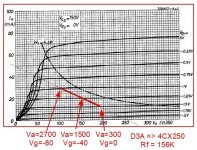
My current favorite driver for this is a high-gm pentode. Here is a D3A driving
a high-gm output tube with Rf=156K, giving an effective load of about 5K ohms.
This uses a cathode resistor to reduce the input sensitivity from 0.5V P-P to
5.6V P-P (2VRMS). My plan is to shift operating points to optimize the small
signal harmonic distortion profile.
Attachments
What it comes down to is:
Find the optimum load for the driver pentode.
Find the optimum feedback for the output pentode.
First of all, CCS load the driver(I disagreed earlier but stand corrected after having done a few sims to prove my theory wrong). Also use an unbypassed cathode resistor.
About the output tube my approach is to add feedback enough to give the tube the same Ri as if it had been triode-strapped.
My guess is that in most cases, the input impedance of the output tube is too heavy as load for the driver.
The solution is simple: Just add an "input series feedback resistor" (15k in my example) that together with the input impedance of the feedbacked output tube gives the optimum pentode-driver load.
Example: Optimum driver load=10k, Input impedance=2k, Input resistor=10k-2k=8k
So what is the optimum load/working point for 6AU6?
Find the optimum load for the driver pentode.
Find the optimum feedback for the output pentode.
First of all, CCS load the driver(I disagreed earlier but stand corrected after having done a few sims to prove my theory wrong
). Also use an unbypassed cathode resistor. About the output tube my approach is to add feedback enough to give the tube the same Ri as if it had been triode-strapped.
My guess is that in most cases, the input impedance of the output tube is too heavy as load for the driver.
The solution is simple: Just add an "input series feedback resistor" (15k in my example) that together with the input impedance of the feedbacked output tube gives the optimum pentode-driver load.
Example: Optimum driver load=10k, Input impedance=2k, Input resistor=10k-2k=8k
So what is the optimum load/working point for 6AU6?
Last edited:
What it comes down to is:
Find the optimum load for the driver pentode.
Find the optimum feedback for the output pentode.
First of all, CCS load the driver(I disagreed earlier but stand corrected after having done a few sims to prove my theory wrong
About the output tube my approach is to add feedback enough to give the tube the same Ri as if it had been triode-strapped.
My guess is that in most cases, the input impedance of the output tube is too heavy as load for the driver.
The solution is simple: Just add an "input series feedback resistor" (15k in my example) that together with the input impedance of the feedbacked output tube gives the optimum pentode-driver load.
Example: Optimum driver load=10k, Input impedance=2k, Input resistor=10k-2k=8k
So what is the optimum load/working point for 6AU6?
Hi Lars,
This is an interesting idea. The series resistor with pentode adds to the load
resistance seen by the pentode but, since it is in series with the driver Ri
there is no significant change in output effective Ri or gain (am I missing
something?)
Where the parallel load resistor (the original circuit) makes a feedback divider,
as does the series resistor with triode Ri, a series resistor with pentode Ri does
not reduce the amount of feedback to the grid. It only changes the voltage
swing at the driver anode.
Neat trick, and another way to independently control the circuit op range.
One more observation, at some point in scaling this up a higher gm driver will
add some needed headroom.
Cheers,
Michael
Lars series compensation resistor for the pentode is interesting. Might have to run a sim to see if it actually improves the pentode linearity notice-ably. Seems like the pentode wouldn't care a whole lot how far it's plate voltage swings except for its very high pentode Mu effect. I think the un-bypassed cathode resistor will still be the main pentode V to I linearizer.
A minor comment on the amplifier anti-triode aspect. To get SE sound out of this thing, the right PL84 output tube should have higher gm than the left one. As it stands, its a self splitting balanced P-P class A "triode" amp. It either needs doubling up the right side tube (and cut DC idle for each) or use a bigger tube or a Mosfet to get to SE sound (.....if that's the goal). Might be feasible to add a Mosfet in parallel with the right side PL84 and provide a bias control knob for its gate, so that one could dial in the amount of gm un-balance. SE <---> P-P control knob. The control pot would likely need to span from a min. DC bias at one end to an overlayed AC tracking signal at the other end to avoid class C operation of the Mosfet.
Don
Last edited:
Lars series compensation resistor for the pentode is interesting. Might have to run a sim to see if it actually improves the pentode linearity notice-ably. Seems like the pentode wouldn't care a whole lot how far it's plate voltage swings except for its very high pentode Mu effect. I think the un-bypassed cathode resistor will still be the main pentode V to I linearizer.
Yes. The higher gm the more linear
A minor comment on the amplifier anti-triode aspect. To get SE sound out of this thing, the right PL84 output tube should have higher gm than the left one. As it stands, its a self splitting balanced P-P class A "triode" amp. It either needs doubling up the right side tube (and cut DC idle for each) or use a bigger tube or a Mosfet to get to SE sound (.....if that's the goal). Might be feasible to add a Mosfet in parallel with the right side PL84 and provide a bias control knob for its gate, so that one could dial in the amount of gm un-balance. SE <---> P-P control knob.
Don
So are you saying that if I construct this from a triode and beam tube of
equivalent gm, that it won't behave as an anti-triode? I'm not convinced.
Isn't it the lower Ri that dominates? Think about the impact on the Zo of
the stage; isn't it 1/2 of the triode alone? I'll need to think about this some
more.. Later...
Michael
Umm, yes the Zo is halved since both tubes are effectively in parallel compared to a single SE tube.
But as far as SE vs P-P, the left tube is developing the drive signal for the right tube on its cathode. Now imagine the right tube having a splitted P-P drive signal slowly brought up on its grid until it nulls out the variation on the common cathodes. Now we have normal P-P operation. Question is, how similar the left side generated cathode drive signal is to the normal P-P splitted right side drive signal. Ie, harmonic content.
I guess with a "triode" on one side and an equal nominal gm pentode on the other, it will take less drive signal amplitude on the pentode grid to equalize the cathodes, since the "plate" feedback on the triode side will be effectively lowering it's gm. So you are right, there is a gm unbalance in this case.
I think this will call for a simulation or actual test to determine how effective. I'm sure a "triode" on one side and an equal gm pentode on the other will have some SE effects, maybe gets one half way to SE. But I'm guessing that fully duplicating the left side harmonic structure in SE mode will require a bit higher gm on the right side.
Don
- Status
- This old topic is closed. If you want to reopen this topic, contact a moderator using the "Report Post" button.
- Home
- Amplifiers
- Tubes / Valves
- My version of the Simple EL84 or rise of the anti-triode.