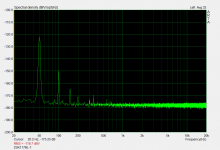
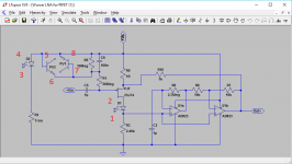
JFET measurements in action.
2SK372GR ~0.8nV/rtHz).
2SK372BL same as 2SK372GR.
2SK369GR ~0.89nV/rtHz
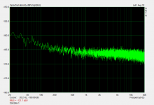
2SK117BL ~1.26nV/rtHz.
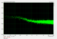
2SK246BL ~4.5nV/rtHz.
2SK715W ~1.26nV/rtHz
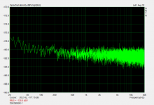
BF862 on TO92 adapter board ~1.12nV/rtHz.
Please ignore the 50Hz stuff for the 2SK117.
It was because the legs were too long and hence the case was not covered fully.
These measurements are extremely sensitive to grounding and shielding.
Taken that into account, the 2SK117 is surprisingly good.
Patrick
2SK372GR ~0.8nV/rtHz).
2SK372BL same as 2SK372GR.
2SK369GR ~0.89nV/rtHz
2SK117BL ~1.26nV/rtHz.
2SK246BL ~4.5nV/rtHz.
2SK715W ~1.26nV/rtHz
BF862 on TO92 adapter board ~1.12nV/rtHz.
Please ignore the 50Hz stuff for the 2SK117.
It was because the legs were too long and hence the case was not covered fully.
These measurements are extremely sensitive to grounding and shielding.
Taken that into account, the 2SK117 is surprisingly good.
Patrick
Attachments
-
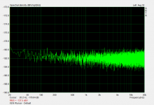 XEN Wurcer 2SK372GR.png63 KB · Views: 852
 -
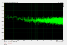 XEN Wurcer BF862.png63.1 KB · Views: 246
 -
 XEN Wurcer 2SK715W.png57.5 KB · Views: 241
 -
 XEN Wurcer 2SK246BL.png58.6 KB · Views: 772
 -
 XEN Wurcer 2SK117BL.png52.1 KB · Views: 778
 -
 XEN Wurcer 2SK369GR.png62.5 KB · Views: 770
 -
 XEN Wurcer 2SK372BL.png62.7 KB · Views: 854
")
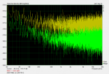
Another interesting one -- 2SK170BL vs. LSK170C.
Yellow is LSK.
And we have measured multiple devices to make sure it is not just a bad example by chance.
Luckily we have lifetime stock of Toshiba's.
Patrick
.
A couple of things for everyone's information.
1) The 2SK715 plot nicely shows the GR noise signature.
2) The 2SK246 probably has a low enough GM that the fixture BW is starting to roll off at 20kHz.
3) The SK170 comparison would be fairer if it took into account the gm. Both 2 & 3 are addressed by something like a QuanTech where the DUT sits before the preamp amplifying it's own noise with its own bias setter. Unfortunately the comparison here would indicate the LSK part would need 4X the current to equal the Toshiba. The LSK's I have are a little closer but beware the first samples of SJ74's are far short on their beta parameter. The more recent date code was far better. Generally I don't fault a FET on noise if it fits the theoretical value (~.7/gm noise resistance) and does not exhibit excess low frequency noise.
For those who don't know the QuanTech allows the user to set the drain current and Vgd and injects a small 1kHz tone to compute gm which is displayed. A nice side project might be a small box to bias both N and P channel devices.
Last edited:
I can supply a scan of the Quantech manual with the circuitry of the later version for anyone who wants to get deep into it. it couples a 4 KHz tone into a loop of wire in the source/emitter essentially (zero Ohms) and then adjusts an AGC circuit for the target output. The AGC level indicates the gain. What makes it more complex is bipolar/FET, anode/cathode voltage, target current or fixed bias and switching between positive and negative devices.
I can supply a scan of the Quantech manual with the circuitry of the later version for anyone who wants to get deep into it. it couples a 4 KHz tone into a loop of wire in the source/emitter essentially (zero Ohms) and then adjusts an AGC circuit for the target output. The AGC level indicates the gain. What makes it more complex is bipolar/FET, anode/cathode voltage, target current or fixed bias and switching between positive and negative devices.
I have the original manual only. BTW the owner offered our sales rep the entire business because his son was not interested, it was something like $100,000 for the name and all documentation/etc.
The manual is available for a short time at this link: https://spaces.hightail.com/receive/90vgi Too big to send other ways.
If you are using this to measure noise for the Jfets I would borrow from the Quantech the selectable resistor to ground. - short, 100 Ohms, 1K Ohms 100 K Ohms and 1 Meg. You can then get voltage noise and current noise. Probably to get meaningful 10 Hz noise you will need a larger coupling cap.
- Home
- Design & Build
- Equipment & Tools
- My version of the G = 1000 low noise measurement amp (for Ikoflexer)