P.S. The closer the poles are, the higher the overshoot. 1.5dB as reported is not that bad, you can leave it as it is and happily live ever after.
Yes, with work it can be critically damped two pole and with carelessness it can motorboat. I also did not really care about a small peaking since it does not really effect settling.
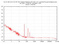
These are the first results of my 2*IF3602 amplifier ( =4*IF3601) at 79 mA
It is kinda disappointing, 190 pV/rt Hz at best, -14.5 dB below 1nV/rt Hz.
I may be off with the gain by a dB; the amp is overcompensated so I miss the 1 MHz
bandwidth goal and it oscillates at 14 KHz with open input. With low impedance
input it is stable. Ferrite gate stoppers have no effect. Resistive gate stoppers
are not tolerable here and did not work anyway.
The amplifier is unconditionally stable when I kill the bootstrap to the cascode, the
measurements have been taken that way.
Given that it is 4:40 here, I better go to bed now.
regards, Gerhard
ps
0 db = 1nV/rt Hz
The baseline on the scope wanders around like hell when the amp. is open, a
sheet of paper does wonders to keep the air from circulating. The TO-5 coolers
are worth their money for the the thermal mass they provide.
Attachments
Last edited:
VO1263 -- someone mentioned the "pole" on the output side.
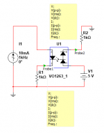
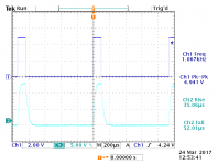
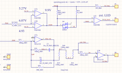
I set up the jig illustrated in figure #1, and derived the results shown in figure #2.
The driver for the LED is the Picotest modulated bias source, I don't know whether it is properly illustrated in the schematic.
I set up the jig illustrated in figure #1, and derived the results shown in figure #2.
The driver for the LED is the Picotest modulated bias source, I don't know whether it is properly illustrated in the schematic.
Attachments
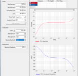
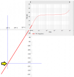
Should we expect that the low frequency gain continues to fall, at the same rate, forever?
For example, should we expect that the gain at 1E-3 Hertz will be approx -122 dB? (as indicated by the yellow arrowhead)
Should we expect that another 3 decades lower frequency (namely, 1E-6 Hz) will produce another (3 x 20dB) = 60 dB less gain: namely -182 dB ??
Is a gain of -182dB functionally equivalent to "zero gain" ??
Attachments
Should we expect that the low frequency gain continues to fall, at the same rate, forever?
For example, should we expect that the gain at 1E-3 Hertz will be approx -122 dB? (as indicated by the yellow arrowhead)
Should we expect that another 3 decades lower frequency (namely, 1E-6 Hz) will produce another (3 x 20dB) = 60 dB less gain: namely -182 dB ??
Is a gain of -182dB functionally equivalent to "zero gain" ??
Setup used the Picotest Bias Injector J2130 Bias Injector, per this application note: https://www.omicron-lab.com/fileadmin/assets/application_notes/App_Note_Optocouplers_V1_0.pdf
Looking through Basso's book, the more classic way of determining the pole of the photo-emitter is to look at the fall time, specified as 472μS in the VO1263 datasheet, loading the photo-emitter with 1MΩ and 15pF. I am not having a lot of luck getting that to work on this end.
Last edited:
Setup used the Picotest Bias Injector J2130 Bias Injector, per this application note: https://www.omicron-lab.com/fileadmin/assets/application_notes/App_Note_Optocouplers_V1_0.pdf
Looking through Basso's book, the more classic way of determining the pole of the photo-emitter is to look at the fall time, specified as 472μS in the VO1263 datasheet, loading the photo-emitter with 1MΩ and 15pF. I am not having a lot of luck getting that to work on this end.
I'm a little confused, the PV's work at DC fine. What AC artifact are you measuring? PV's can have settling tails causing bumps in low frequency response.
Last edited:
Bandwidth limitation on the Picotest J2130A
OK makes sense. Our problem is that some very cheap PD's have charge that wanders off and appears back at the terminals very slowly. This means that in strobed applications there is a slight gain change vs sampling rate (the flash rate on the green LED on the back of your health watch). You would be stunned at the deal the Mexican gov. gave some folks to fab all their large area PD's in Mexico.
Pole at 7-10 kHz
That's why you get the big bux
") For me it's an avocation, for you a profession.
For me it's an avocation, for you a profession.Wouldn't think that has much to do with the slight belly bulge from 10 to 20 Hz.
> Why, silly hare, are you fleeing from the fierce jaws of the lion now grown tame?
Ze hare is very high, and ze sauce is very rich with truffles, anchovies, Grand Marnier, bacon, and cream.
Sorry, it reminds me every time...
But Mr. Creosote without the blood it just won't be right.
That's why you get the big bux
Wouldn't think that has much to do with the slight belly bulge from 10 to 20 Hz.
Second LF pole I was talking about is given by the 100nF cap filtering the opto out and whatever impedance it sees across, mostly the opto source impedance. The servo pole is in origin, this pole is displaced on the frequency axes, like any RC cell response. So you need a zero to compensate it, leaving only the pole in origin. Add a zero, restore the flat freq response, but keep RC filtering the optocoupler output. A resistor in series with the servo cap works a treat, you just noticed the bump going down. Further tuning the value, you'll get the LF response flat (or critically damped if you prefer).
Back to bed now...
We had some bank holidays here, so i could spend some time on the Fet low noise amplifier. No matter what I do, it has somewhere negative input impedance and it
will oscillate with the right inductor across the input.
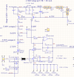
Circuit is nothing fancy: CS fet stage, cascode, TIA for loop gain, feedback 1000:1 or so
back to the source. The cascode is biased by a current source.
The usual remedy, a base stopper resistor defies the purpose of a low noise amplifier.
So far, I have made several versions: one with 2 pairs of IF3602 or many BF862 and
a bipolar cascode and a different one with upto 25 pcs. 2SK2394-6 or BF862 , each
with a MMBFJ310 cascode transistor of its own. That is easy because the 310 gate
can directly be attached to the 2SK2394 source without any ado about biasing.
I have used only 15 pairs because I didn't have enough MMBFJ310.
The IF3602 version was kinda hopeless already without any attempt at bootstrapping;
the 2394/310 pair has the bootstrapping for free and looks much friendlier.
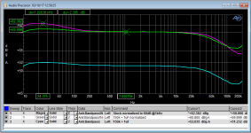
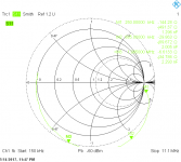
I measured the input inpedance with a R&S ZVB8 vector network analyzer; sorry
that its lowest frequency of operation is 150 KHz (really specced at 300KHz).
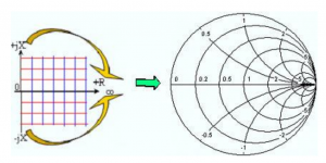
I measure S11 of the amplifier and get a Smith diagram. That is really an impedance
plot with real values on the X-axis, inductance in the upper half and capacitance
in the lower. It is morphed to a circle so that the display goes from 0 to infinity on
a finite piece of paper. 50 Ohm without LC is in the middle of that unit circle. That
could be normalized for other impedances, but 50 is standard.
Everything in the circle has a positive real part, everything outside has a negative
real part. That can happen only with active circuits, where the analyzer gets
more power back from the circuit than it feeds into it.
The picture of the morphing is from the analyzer handbook, I think this is fair use.
The Smith chart is from the IF3602 amplifier; the greenish line leaves the unit
circle already near Marker 1, and at 2 MHz it reenters the passive region, so above
that the amplifier could not oscillate from any input impedance presented.
Sorry for the colours. The markers display the computed impedance and L/C
at their frequency.
For the 2394/310 pairs, the line also leaves the passive circle, but it stays much closer
to it, so it probably would take less effort to stabilize it completely.
I have read Samuel Gröner's amplifier article in Linear Audio. He also seems
to have problems with negative input impedance but he looses
me when he writes about negative capacitance. Negative capacitance is
inductance, nothing bad by itself. The problem is the negative real part.
No amount of additional "positive" capacitance could cure that; I tried up to
100 nF.
I have also tried Würth 600 Ohm 0805 beads as gate stoppers; they don't damp
anything, they behave like pure inductors. One bead for all 15 transistors made
the input inductive at high frequency, the trajectory went clockwise to the upper half,
following the circle.
Somehow I feel it is wrong to call the input fet common source. The drain
looks into the low impedance of the cascode and the source follows the
input voltage by the action of the feedback. So the FET does not see 0.2 Ohm
to ground but a synthesized current source. From its point of view it could
be called source follower at any time.
Any ideas about how to tame such a thing?
I don't want to take control of this thread, but I think here are the right
people for good S/N
will oscillate with the right inductor across the input.
Circuit is nothing fancy: CS fet stage, cascode, TIA for loop gain, feedback 1000:1 or so
back to the source. The cascode is biased by a current source.
The usual remedy, a base stopper resistor defies the purpose of a low noise amplifier.
So far, I have made several versions: one with 2 pairs of IF3602 or many BF862 and
a bipolar cascode and a different one with upto 25 pcs. 2SK2394-6 or BF862 , each
with a MMBFJ310 cascode transistor of its own. That is easy because the 310 gate
can directly be attached to the 2SK2394 source without any ado about biasing.
I have used only 15 pairs because I didn't have enough MMBFJ310.
The IF3602 version was kinda hopeless already without any attempt at bootstrapping;
the 2394/310 pair has the bootstrapping for free and looks much friendlier.
I measured the input inpedance with a R&S ZVB8 vector network analyzer; sorry
that its lowest frequency of operation is 150 KHz (really specced at 300KHz).
I measure S11 of the amplifier and get a Smith diagram. That is really an impedance
plot with real values on the X-axis, inductance in the upper half and capacitance
in the lower. It is morphed to a circle so that the display goes from 0 to infinity on
a finite piece of paper. 50 Ohm without LC is in the middle of that unit circle. That
could be normalized for other impedances, but 50 is standard.
Everything in the circle has a positive real part, everything outside has a negative
real part. That can happen only with active circuits, where the analyzer gets
more power back from the circuit than it feeds into it.
The picture of the morphing is from the analyzer handbook, I think this is fair use.
The Smith chart is from the IF3602 amplifier; the greenish line leaves the unit
circle already near Marker 1, and at 2 MHz it reenters the passive region, so above
that the amplifier could not oscillate from any input impedance presented.
Sorry for the colours. The markers display the computed impedance and L/C
at their frequency.
For the 2394/310 pairs, the line also leaves the passive circle, but it stays much closer
to it, so it probably would take less effort to stabilize it completely.
I have read Samuel Gröner's amplifier article in Linear Audio. He also seems
to have problems with negative input impedance but he looses
me when he writes about negative capacitance. Negative capacitance is
inductance, nothing bad by itself. The problem is the negative real part.
No amount of additional "positive" capacitance could cure that; I tried up to
100 nF.
I have also tried Würth 600 Ohm 0805 beads as gate stoppers; they don't damp
anything, they behave like pure inductors. One bead for all 15 transistors made
the input inductive at high frequency, the trajectory went clockwise to the upper half,
following the circle.
Somehow I feel it is wrong to call the input fet common source. The drain
looks into the low impedance of the cascode and the source follows the
input voltage by the action of the feedback. So the FET does not see 0.2 Ohm
to ground but a synthesized current source. From its point of view it could
be called source follower at any time.
Any ideas about how to tame such a thing?
I don't want to take control of this thread, but I think here are the right
people for good S/N
Attachments
- Home
- Design & Build
- Equipment & Tools
- My version of the G = 1000 low noise measurement amp (for Ikoflexer)