so -last iteration can be
http://www.diyaudio.com/forums/attachment.php?s=&postid=789081&stamp=1134481790
use whatever you have (bigger ) for 'lytics,put 22 to 100nF in para with each
use whatever you have of darlingtons in drawer (at least 45Vc-e)
use any diodes in output
but-you must use some sort of mains filtration
we don't need that trim pot on main pcb,just temporary for DC nulling ,and then fixed resistor?
thoughts?
now we (steen and my humbleness) need "third opinion" regarding shunt reg etc,speaking of sort of "group project".
I'll go with this shunt reg (again-tnx to R.Elliot) ,without cap multiplier......
now I can try my BOZ,at last ...........


who will have post No.350?
ps.and-steen-Iq IS ~10mA;
same as in any push pull output amp when we say that Iq is 1A,for instance;
1A in both halves,but still 1A overall.
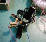
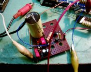
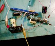
funny- NS10 ,at least with my test listenin' level (pretty low electrically,just because later connected SS Alnicos are more than 90db/W/m) worked flawessly even with just +- 3V5 supply

Just a hint Steen,
Maybe the problem with Choky’s shunt reg lays on a low Voltage provided by the PSU, voltage starving should I called it.
Which voltage do you have at the first smoothing cap? (before the first R). Both Pi resistors -at arround 100R- will lower the voltage quite a bit depending on the current draw wich I estimate at 80 to 100 ma.
Besides measuring with DVM you can try a lower voltage zener stack and see what happens")
Maybe the problem with Choky’s shunt reg lays on a low Voltage provided by the PSU, voltage starving should I called it.
Which voltage do you have at the first smoothing cap? (before the first R). Both Pi resistors -at arround 100R- will lower the voltage quite a bit depending on the current draw wich I estimate at 80 to 100 ma.
Besides measuring with DVM you can try a lower voltage zener stack and see what happens
choky said:
we don't need that trim pot on main pcb,just temporary for DC nulling ,and then fixed resistor?
thoughts?
Agree 100%, is the way to go
And no need to null compleatly since we have a cap at the output. If someone uses a lytic just leave a +3V
apassgear said:Just a hint Steen,
Maybe the problem with Choky’s shunt reg lays on a low Voltage provided by the PSU, voltage starving should I called it.
Which voltage do you have at the first smoothing cap? (before the first R). Both Pi resistors -at arround 100R- will lower the voltage quite a bit depending on the current draw wich I estimate at 80 to 100 ma.
Besides measuring with DVM you can try a lower voltage zener stack and see what happens
as I said-absolute minimum is STIFF 35 volts on input (first 100 ohm resistor)
with this ,current summ is easily solved- 35-25,7/200 ohms=46,5mA
~10 for preamp
~10 for zenners
rest for darlington lunch hehe
I tried today (ystrdy?) with 45 V input ,without any problem (heat ,hum ,buzz,anything)
in any case-if we presume some mains variations,I'll not go under 40-45 V on reg input
on case of stable mains feed,35V will do the job
just to be eeky peeky
one can increase base resistor to 220 Ohms and spare few more milliamps for active burning in transistor
in that case current through zenners will be under 5mA,so 5mA will be transferred to transistor.
I am not so used to spare on milliamps,even I'm primary tube oriented... my preamp use no less than 20mA per channel and also 25mA in shunt per channel.......

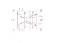
Well, here is an attempt to use the TL431 as a voltage ref.
Seems to be somewhat extreme in certain aspects but is not, remember that the PSU is in the signal path so whatever we can do to benefit it will be reflected sound wise. Myself will replace R1 with a choke when it’s my turn to do this extraordinary pre.
Please take in consideration that the circuit has not been tested, any suggestion is welcomed. Just don’t
apassgear said:Well, here is an attempt to use the TL431 as a voltage ref.
Seems to be somewhat extreme in certain aspects but is not, remember that the PSU is in the signal path so whatever we can do to benefit it will be reflected sound wise. Myself will replace R1 with a choke when it’s my turn to do this extraordinary pre.
Please take in consideration that the circuit has not been tested, any suggestion is welcomed. Just don’t
looks good;
as I said earlier-only ears can decide what is better-simple one transistor +zenner stack or TL431 (with or without transistor) route...
in any case-just remember-in case that you want to implement choke,resistor in series have role to burn excessive voltage;
if you calculated that you need 100 ohms for presumed and needed current (what you splitted in two 47) then you need again 100 ohm minus DCR of choke-no less....
all that in case that you don't want more current burning in transistor
etc
etc
link to DC blocker-mains filter thread- article-post etc
http://www.diyaudio.com/forums/showthread.php?postid=780865#post780865
'grats for post 350
ps-I always forget to ask-is that Philips in your avatar pic?
http://www.diyaudio.com/forums/showthread.php?s=&threadid=63158
o tempora,o mores
world is small
I didn't checked yet.....
o tempora,o mores
world is small
I didn't checked yet.....
Choky, great work on that NS10 proto Now thats what I call DIY. Now that you mention the mains noise; I can clearly hear my soldering iron making noise in the speakers when its turned on in my workroom! I can also hear a bit noise from the fridge and so on when it turns on and off. So it might be a good idea to look into that mains filtering as you suggest
Steen
Now thats what I call DIY. Now that you mention the mains noise; I can clearly hear my soldering iron making noise in the speakers when its turned on in my workroom! I can also hear a bit noise from the fridge and so on when it turns on and off. So it might be a good idea to look into that mains filtering as you suggest Looks good, Tony. Nice drawingWell, here is an attempt to use the TL431 as a voltage ref.
Steen
choky said:
looks good;
as I said earlier-only ears can decide what is better-simple one transistor +zenner stack or TL431 (with or without transistor) route...
in any case-just remember-in case that you want to implement choke,resistor in series have role to burn excessive voltage;
if you calculated that you need 100 ohms for presumed and needed current (what you splitted in two 47) then you need again 100 ohm minus DCR of choke-no less....
all that in case that you don't want more current burning in transistor
etc
etc
link to DC blocker-mains filter thread- article-post etc
http://www.diyaudio.com/forums/showthread.php?postid=780865#post780865
'grats for post 350
ps-I always forget to ask-is that Philips in your avatar pic?
Your right Choky, in order to use a choke the voltage coming from the PSU has to be adjusted acordingly to the coil you will be using.
Yes, the avatar is a strange looking Philips 5", limited edition I guess.
Gain, Buzz, BD's,
Hello everyone,
I need to knock up a quick pre-amp to put my LM3886 amps through their paces, and given that I am not building an Aleph clone, I thought something from Mr. Pass would still be a "good thing."
I am gathering parts up, hopefully should get most at Dick Smith's or Jaycar before Christmas, but in the meantime some questions:
1. What is the gain of this circuit?
2. If I have to change the gain a bit, what is the best way to do it?
3. What are the BD's that everyone is talking about (Stenoe started it I think)?
4. Stenoe, have you managed to get rid of the buzz? Was it "current starvation" of the regulators as suggested by someone else?
5. Is the LM317/337 power supply solution from Rod Elliott a usable or a good solution for this pre-amp?
Thanks for your assistance.
Regards,
Mark Walsh.
Lots of questions
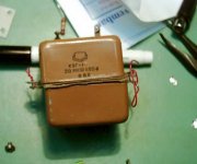
I have a really nice potted EI trafo, that I might try for this preamp.One other suggestion to get a less noisy supply is using an EI trafo insted of those toroids.
Hi Mark, you cant go wrong with the NS10. I used it a lot in my workroom for driving a OPA549 chipamp. Sounds much better than the OPA627/BUF634 I used before;-) Regarding your questions, I dont remember the excact gain or how to change it, but I can tell you it has enough gain for all my poweramps. Thats 4 different amps. It drives even Zen amps with ease.I need to knock up a quick pre-amp to put my LM3886 amps through their paces
BD's are normal BD139/BD140 transistors
I still have a little buzz when using the shuntreg, maybe its mains noise as suggested.
Elliots LM317/LM337 would do great
I am using something similar with good results.Steen
But there's more!
Thanks, Stenoe.
To get a quick prototype up and going before/during Christmas, could I just BC549's and BC559's? (I presume that these transistors would not cope with a really low input impedance in the power amp, or would there be greater problems?)
I simply cannot even get BC560's any more in Australia, even from Farnell or RSComponents, and anything as "esoteric" as an MPSA18 or PN4250/2N4250 is right out of the question .
(I could probably find equivalents from them, but even so I would not get the parts til after Christmas.)
Question 1: Tell me more about C4 (from base to collector of Q1) ... which post can I read about it in; what is it for; what is its value?
That buzz would drive me MAD with frustration, given all the work done on the project.
Question 2: I am thinking about leaving out C2 for the time being given input capacitors on my LM3886's. But the input capcitance is only 2.2 uF on the LM3886 amps.
a) What would happen then?
b) If I leave out C2, what would I do with R11 and R10?
Question 3:
Was your previous pre-amp the one designed by Carlosfm (and one preceding chappie whose name I cannot remember) based on the OPA627/BUF634?
Best regards,
George.
- Status
- This old topic is closed. If you want to reopen this topic, contact a moderator using the "Report Post" button.
- Home
- Amplifiers
- Pass Labs
- My Take on Threshold NS10