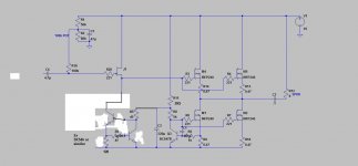
OK, now I'm lost. Can you post an updated schematic to compare?The PCB layout is attached ...
Or a couple of J202 in parallel in the meantime for testing.If I want more current I need to switch fets. I'm going to try a J203.
Also, IMHO, the top fet should have at least the same Idss as the bottom one, otherwise it will have positive Vgs, causing gate current.
OK, now I'm lost. Can you post an updated schematic to compare?
Oh dear.
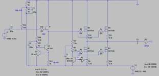
It's pretty much the same as my first post except the speaker return is to ground and I'm only using 2 pairs of output fets rather than 3 (M1 + M3, M4 + M6):
Attachments
transconductance of inputs is critical
use either J309 or J310 , with adequate source resistor for lower one
observe dissipation and don't use less than 5mA through them
in fact - use Jfet for upper one and any CCS you want , instead lower one
Thanks ZM,
I will definitely up the current.
I used the J202 as they are made for audio use so I assumed they would be better. Is that incorrect? Could it really be that critical in this source follower application?
They also have a 40v rating which is necessary for this particular application as they see 35v across them at turn on.
The J203 would be good if I want more current too I think. As soon as I have some new fets I'll keep experimenting.
Last edited:
Thanks ZM,
I will definitely up the current.
I used the J202 as they are made for audio use so I assumed they would be better. Is that incorrect? Could it really be that critical in this source follower application?
They also have a 40v rating which is necessary for this particular application as they see 35v across them at turn on.
The J203 would be good if I want more current too I think. As soon as I have some new fets I'll keep experimenting.
I'm using J309 or J310 in
 and I'm satisfied with them , comparing to 2SK170 or even 2SK369
 I don't see powering up as problem , regarding voltage ;
thinking about CCS - you can use something as on attached schm
of course - you'll loose slightly to rail to rail drive , comparing to solution with one jfet CCS , but who cares ....
edit : play a little with mosfet gate resistors , if you want to alter leading edge of output oscillogram ; there is no use looking at gates
Attachments
Last edited:
Hi Zen Mod,
Nice photoshop work with the schematic there! I had thought of using a bipolar ccs, but the jfet ccs is so neat! I really don't want to lose any voltage swing if possible as I already only have 30V P-P. It may turn out to be my only choice though. I need to do some simulations.
Thanks for your input on the JFETs. What p channel device do you recommend (for an F5).
Thanks again,
Greg.
Last edited:
Hi tsz,
No I haven't tried that. Is there any reason to?
The speaker return is connected to ground (unlike the schematic).
The PCB layout is attached (but I'm only using 2 output pairs, not 3).
Nah, not if the speaker return is connected to ground. I just thought it looked odd with different references for input and output (very poor PSRR I imagine).
What made you abandon the constant current draw approach?
thanks tsz,
I haven't abandoned the approach, I'm just not using it for this initial testing phase. In fact when I get this circuit working smoothly I will be redesigning it with a negative rail and constant current as per godfrey's circuit here:
http://www.diyaudio.com/forums/solid-state/185081-constant-current-pros-cons-5.html
Looks promising I think.
Hi Zen Mod,
Nice photoshop work with the schematic there! I had thought of using a bipolar ccs, but the jfet ccs is so neat! I really don't want to lose any voltage swing if possible as I already only have 30V P-P. It may turn out to be my only choice though. I need to do some simulations.
Thanks for your input on the JFETs. What p channel device do you recommend (for an F5).
Thanks again,
Greg.

just plain MS Paint ......
one JFET CCS isn't neat , it's just good enough ..... but - as all other things , if your compromise demands that , that's best solution .
for F5 - I have impression that "original" 2SK170 and 2SJ74 are still easy to find , even if not exactly cheapest ...
ask Blues for them
if you insist on using other ones - try J309 ( or J310) & J271 , but you'll need substantial source resistors for them - that's tricky part of game
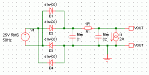
For simple unfiltered supplies, there's a simple rule of thumb:How much ripple do we typically see in a heavily engineered non regulated PSU for a Class A amp?
With a 10000uF reservoir cap, an average current of 1A causes about 1V pk-pk of ripple.
Doubling the current doubles the ripple.
Doubling the cap halves the ripple.
Even a simple RC filter makes a big difference though. It doesn't just reduce the total ripple, it gets rid of the higher harmonics so you're left with "hum" rather than "buzz".
If you play in the simulator with a circuit like the one below, you can see what to expect. Mind out for the power dissipation of the resistor, and the DC voltage drop across it.
p.s. Sorry to answer in the wrong thread; I just wanted to get away from the trolling there.
Attachments
Thanks Godfrey,
Yeah, the other thread has started go haywire hasn't it? It's a shame because there's some good info there.
I've actually made that exact model before and noted only a few mv of ripple with the CRC filter and several amps of current. I always model them with a transformer with inherent inductance and resistance, but never know how realistic my models are. I also get the series resistance and inductance from the datasheets for the capacitors.
I was just interested to know what people are actually measuring in real life power suppplies, ie how do they compare to the models? I don't have enough experience to know yet - time to scope mine I guess!
one JFET CCS isn't neat , it's just good enough ..... but - as all other things , if your compromise demands that , that's best solution .
Oh really? I thought the JFET ccs was pretty good. This is actually good news. I will redesign the circuit with a bipolar ccs immediately. Transistors are cheap and common.
Excellent, then you can use both jfets in parallel in the "J1" position, for more current handling.Oh really? I thought the JFET ccs was pretty good. This is actually good news. I will redesign the circuit with a bipolar ccs immediately. Transistors are cheap and common.
Yes,
Does this mean a bipolar CCS would also be better for the output stage? Similar to the Pavel follower seen here:
Project 83 - MOSFET Power Follower
What is the best practice for paralleling JFETs? Should a source resistor be used?
Does this mean a bipolar CCS would also be better for the output stage? Similar to the Pavel follower seen here:
Project 83 - MOSFET Power Follower
What is the best practice for paralleling JFETs? Should a source resistor be used?
off course - you can reference speaker to + PSU , too ;
bip CCS isn't better than Mosfet , point was in that simple Jfet CCS is worse than somewhat more complex CCS , of any sort
drawback of more complex CCS , as I wrote previously , is that it needs little more voltage headroom to work
anyway - rail to rail thing is over-hyped - who needs amp screaming all the way all the time ....... don't use force , use a bigger hammer
for paralleling jfets - use small source resistors ( say 4R7 ) but be aware that every time you place source resistor , you're messing with Jfet's xconductance
Thanks Zen Mod.
So true. I scoped my speakers and it turns out my listening levels are seldom over a few watts. If I get 20W RMS I'll be happy.
off course - you can reference speaker to + PSU , too ;
anyway - rail to rail thing is over-hyped - who needs amp screaming all the way all the time ....... don't use force , use a bigger hammer
So true. I scoped my speakers and it turns out my listening levels are seldom over a few watts. If I get 20W RMS I'll be happy.
Ok, here is the circuit I am hoping to go with. You will note that it uses a negative supply for constant current draw from the PSU. Things are looking good I think.
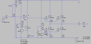
Current through input fet (J202) ~10mA, dissipation ~134mW. This is a 600mW device so I assume this is OK. No parallel jfets needed. Could I go with even higher current?
Current through Q1 ~10mA, dissipation ~210mW - a little high prehaps? Maybe a BD139 would be better?
Current through Q2 ~ 4mA, dissipation 6.2mW - good?
Suggestions and flames welcome!
Attachments
Last edited:
- Status
- This old topic is closed. If you want to reopen this topic, contact a moderator using the "Report Post" button.
- Home
- Amplifiers
- Pass Labs
- My take on the F4 - advice needed