hmm well overal i do really like the simplicity of the driver. 10 magnets and some foil and you got the main ingredients of w pretty good driver ")
Btw where do you make your foil? some external company ? what are the costs if i may ask. since i wonder if they also do other foils like mylar etc? or any other laminates.
Btw where do you make your foil? some external company ? what are the costs if i may ask. since i wonder if they also do other foils like mylar etc? or any other laminates.
"-simplicity of the driver. 10 magnets and some foil and you got the main ingredients of a pretty good driver "
That's the general idea! Something simple that works wonders!
Yes, the foils are made as a favor by a friend who owns such a company that makes
foils and complete drivers (ribbon tweeters mostly) for him and other manufacturers.
He has asked to keep it quite...so i will not tell the name...sorry!
Even like this... after the prototype testing and finalization of the design (meaning scrap some foils/magnets/frames and machined steel plates) i will have to order them in batches of 10...over 1000 euros a batch...
I have some rough estimation of metal /plastic/CNC costs and for the 72 magnets per speaker...
My friend says that i am crazy to build it the way i do... and that it will not be financially viable...
My answer is: "Have you seen the prices for Raven and Raal ribbons?"
How about the prices for the used replacement planars for eg Infinity speakers...
We are talking for 30 years old drivers that sell in a range of anywhere between 500 and 1500 euros...
Well...in comparison to the 200+ euros for a refoil of my XX-500s...it's a bargain.
When you ask for a custom thickness, a custom aluminium trace shape and thickness
and for a possibility of sandwich foil construction...you have to pay!
I just received a photo:
When you ask for a custom thickness, a custom aluminium trace shape and thickness
and for a possibility of sandwich foil construction...you have to pay!
I just received a photo:
Attachments
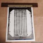
I said that the test foils are going to be in PE that is a bit cheaper. I have asked for four foils for my tests.
These will be 22X17 (a bit short) ...hence the lower impendace (6.5 Ohms).
Probably the final version will be a bit longer so that the 6.5 Ohms will rise to 8 Ohms...
These will be 22X17 (a bit short) ...hence the lower impendace (6.5 Ohms).
Probably the final version will be a bit longer so that the 6.5 Ohms will rise to 8 Ohms...
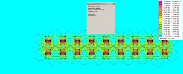
ok but did you FEMM your magnet motor already? since you are pouring in some serious money. i advise you to look into it. else give the some dimension i can make a small simm of a few rows.
but i need to know size magnet, grade, and grade of steel. and gap distance between magnets and the magnet gap between front and rear.!
but in the end you should just play with it a bit. thickness of steel width between magnets , etc.
but i need to know size magnet, grade, and grade of steel. and gap distance between magnets and the magnet gap between front and rear.!
but in the end you should just play with it a bit. thickness of steel width between magnets , etc.
Last edited:
I know and i have talked with him about that.
That's why i have asked for the whole layout of the driver with the external dimensions and the screw positions so that i will not overdo it when attaching to frame.
He said to prefer pressure sensitive glues than contact (solvent) types.
Thanks for the FEMM offer.
You will receive a pm...
That's why i have asked for the whole layout of the driver with the external dimensions and the screw positions so that i will not overdo it when attaching to frame.
He said to prefer pressure sensitive glues than contact (solvent) types.
Thanks for the FEMM offer.
You will receive a pm...
Hmm...it's a long story.
I vision this mainly for stacking and 8 Ohms is a nice number!
As a parallel pair you get a reasonable 4 Ohms (that you can drive with tube amps!) and as a quad you have again 8 Ohms in a parallel/series configuration.
I have certain speaker designs in mind...
I vision this mainly for stacking and 8 Ohms is a nice number!
As a parallel pair you get a reasonable 4 Ohms (that you can drive with tube amps!) and as a quad you have again 8 Ohms in a parallel/series configuration.
I have certain speaker designs in mind...
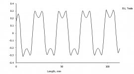
Here i made a sim. You can see the concern i had with the width of the rows(and thus open area) the gap is not very even.
my advice would be decrease space between magnets you get higher and more even field strength. this means either making it less wide or add more magnets.
this is a model with Neo40's
metal is thick enough not even close to saturation.
just my 2 cents
btw it will work as it is, just something you can think about if its not to late to change small things in the design?
Attachments
Last edited:
I see your point...although i would like to see a description of what the ideal would be (and how much is this feasible in the real world!).
Perhaps you could shed some light in the subject.
You say this is calculated with N40 Neos.
As i mentioned i have on order up to N50. How much would this change the picture?
The same goes with the spacing between opposing magnets.
I have provision for 5mm(+/-2.5mm) and 4mm(+/-2mm).
Can you make a FEMM study with this scenario (N50s AND 4mm distance between opposing magnets) for comparison?
At the moment the magnets are spaced out at 9mm.
If i was forced i could bring them closer by 1mm (down to 8mm)
i would need a set of 5mm wide X 4mm deep magnets.
How much better the picture would be?
Thank you for taking the time to look into this deeper!
TNT has used FEMM since hes using the
hmm thats allot of work to be honest femm is a retarded program with a gui from late 80's it is really no fun to do.
i can send you my model and you can adjust it yourself.
N50 wil make it a bit better but its not the distance from magnet to magnet (from front to back) that is the problem. it is more the magnet to magnet on the same plate distance. when you think of it its pretty obious, you got square magnets, and the opposing distance is 4 mm and from row to row, its more then double that. using neos 50 will results in the same uneven field as fas as i know but stronger i would get them closer together lets say from 9 to 6 or 7. ofc best way is to model it ofc. but i hardly model this stuff for myself since its a pain in the *** to work with femm.
you first have to set dots on the right place then put lines in between until its closed, then you put a green marker that tells the program what material it is/ steel/magnet etc if you select such green marker you can press space and you can change the properties of the marker and properties of the magnet direction for instance.
you even have to do this for you working area. so you mark a big slap with 4 dots then close the square with lines then put a green marker in it to tell the program the inside will be in AIR . and in this square i am gone draw the motor etc.
then if you make one stupid mistake you have to destroy half of your drawing. also looking at the gridd counting dods makes me sick haha i am happy and willing to help but i wont sym all of those sorry. download femm open my session, and maybe a skype runtrough will get you up and running ?
hmm thats allot of work to be honest femm is a retarded program with a gui from late 80's
it is really no fun to do. i can send you my model and you can adjust it yourself.
N50 wil make it a bit better but its not the distance from magnet to magnet (from front to back) that is the problem. it is more the magnet to magnet on the same plate distance. when you think of it its pretty obious, you got square magnets, and the opposing distance is 4 mm and from row to row, its more then double that. using neos 50 will results in the same uneven field as fas as i know but stronger
i would get them closer together lets say from 9 to 6 or 7. ofc best way is to model it ofc. but i hardly model this stuff for myself since its a pain in the *** to work with femm. you first have to set dots on the right place then put lines in between until its closed, then you put a green marker that tells the program what material it is/ steel/magnet etc if you select such green marker you can press space and you can change the properties of the marker and properties of the magnet direction for instance.
you even have to do this for you working area. so you mark a big slap with 4 dots then close the square with lines then put a green marker in it to tell the program the inside will be in AIR . and in this square i am gone draw the motor etc.
then if you make one stupid mistake you have to destroy half of your drawing. also looking at the gridd counting dods makes me sick
haha i am happy and willing to help but i wont sym all of those sorry. download femm open my session, and maybe a skype runtrough will get you up and running ?
Last edited:
- Home
- Loudspeakers
- Planars & Exotics
- My own magnetic planar driver