@soundofvoid:
As you have taken a number of different commercial drivers apart, can you then give an estimate on how thick the diaphragm materials have been used for each of the designs alu and backing material?
In my first attempt I used very thin backing material think it was 6 mu, so not easy to work with at all .... but good for getting output at high frequencies. For lower freqs it will astually be better with a heavier material thereby giving a lower res freq.
@ Baldin : As a spacer material i will use bakelite sheet...since it's really hard and stable in dimension regardless of temperature.
I need to be able to tap and die it at the top so that the tensioning screws can screw against the metal rods.
In fact any machinable plastic that the foil can be glued on could be OK.
Regarding thickness...for mid drivers usually it's 20 micron to 30 micron for the foil (Kapton).
For mid bass drivers FS41 (40 micron) and in the new version L-EMIM it's composite 30 kapton (from two layers) and reaches around 115 micron if you add the adhesive layers and aluminum trace...
@ Baldin : As a spacer material i will use bakelite sheet...since it's really hard and stable in dimension regardless of temperature.
I need to be able to tap and die it at the top so that the tensioning screws can screw against the metal rods.
In fact any machinable plastic that the foil can be glued on could be OK.
Regarding thickness...for mid drivers usually it's 20 micron to 30 micron for the foil (Kapton).
For mid bass drivers FS41 (40 micron) and in the new version L-EMIM it's composite 30 kapton (from two layers) and reaches around 115 micron if you add the adhesive layers and aluminum trace...
bakalite may be harder to find then HPL? you can tap HPL but it depends a bit on the brand and the size of screw used. never seen bakalite somehwere among the plastics. dont know why its pretty nice stuff
Sorry for no news for so long!
My CNC guy has had a back problem and has left me high and dry for 2 weeks now!
I have contacted another CNC shop and will meet with them next Monday maybe...
In the meantime i have done some work on the designs.
Regarding the issue of actual percentage of foil surface vibrating...i have an idea that i want to check with you guys...
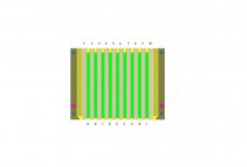
It is "customary" to have the first group of traces BETWEEN the first two rows of magnets and the last group of traces BETWEEN the last two rows of magnets.
What if the first line of traces was placed OUTSIDE the first row of magnets and the last outside the last row?
This way the moving force would apply earlier (nearer to the sides) facilitating the movement of a larger portion of the foil area.
Am i wrong?
Please see attachments for explaining.
In the 1rst schematic (green are the magnets) the first VISIBLE traces would be the #2 and the last the #9.
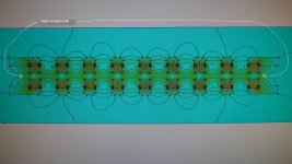
The next schematic shows the magnetic power that i want to exploit.
Opinions?
My CNC guy has had a back problem and has left me high and dry for 2 weeks now!
I have contacted another CNC shop and will meet with them next Monday maybe...
In the meantime i have done some work on the designs.
Regarding the issue of actual percentage of foil surface vibrating...i have an idea that i want to check with you guys...
It is "customary" to have the first group of traces BETWEEN the first two rows of magnets and the last group of traces BETWEEN the last two rows of magnets.
What if the first line of traces was placed OUTSIDE the first row of magnets and the last outside the last row?
This way the moving force would apply earlier (nearer to the sides) facilitating the movement of a larger portion of the foil area.
Am i wrong?
Please see attachments for explaining.
In the 1rst schematic (green are the magnets) the first VISIBLE traces would be the #2 and the last the #9.
The next schematic shows the magnetic power that i want to exploit.
Opinions?
Attachments
Well 2 Things ,
1 you have an uneven field there since there is only one magnet row, not good for distortion.
2 placing the coil so close to where the foil meets the spacer results in the foil almost not able to move or at least not evenly. So the gain is minimal
I think it is not an trace. Versus foil dielma over the entire foil but in the area that is gone be active. No need to move that coil.
Also it is more pronounced in higher frequency, the foil,,/Trace ratio in a bass panel there is almost 9 mm from wire to wire and it's no problem, the higher in frequency you go the better the ratio must be or it will sound hollow, that's just my observation
Last edited:
Looking at the femm I wonder:
- The material in the housing will it be "magnetic" and if so work a s a return circuit - how will that effect the simulation?
- The housing will bulge. How will that effect the field over the traces? Maybe you would like to estimate it and introduce that "curved" mounting in the model?
To drive the membrane close to the attachment point is tricky. Wasted energy that still need to go somewhere - question is where? Heat?
//
Ηmmm...tbh i've never seen anything else but steel used as a housing.
In some drivers just painted black(!) with no extra treatment to prevent corrosion!
The FEMM study shows how the iron will react to the magnets attached.
It becomes magnetized and sucks the magnetic energy of the attached pole.
I would say that it is a good thing since there is no need for stray magnetic energy projecting from the speaker's front and back.
We want it "dense" and "compressed" where it counts: between the steel plates.
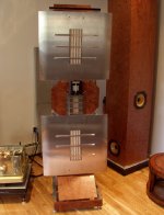
As for the "bulging":yes it will bulge...my guess is that it will be minimal, increasing the
distance between the plates/magnets (mainly in the center that is the "weakest" spot) by a few tenths of a mm.
If it is more than this (to prevent a weakening magnetic field) i will reinforce the steel frames at the center with an external horizontal steel bar cut in triangular or trapezoidal shape.
Something like the one pictured:
In some drivers just painted black(!) with no extra treatment to prevent corrosion!
The FEMM study shows how the iron will react to the magnets attached.
It becomes magnetized and sucks the magnetic energy of the attached pole.
I would say that it is a good thing since there is no need for stray magnetic energy projecting from the speaker's front and back.
We want it "dense" and "compressed" where it counts: between the steel plates.
As for the "bulging":yes it will bulge...my guess is that it will be minimal, increasing the
distance between the plates/magnets (mainly in the center that is the "weakest" spot) by a few tenths of a mm.
If it is more than this (to prevent a weakening magnetic field) i will reinforce the steel frames at the center with an external horizontal steel bar cut in triangular or trapezoidal shape.
Something like the one pictured:
Attachments
Well try to push the foil al that location to the xmax you wont reach it before you break the Mylar")
No way near the Xmax! If the Xmax is a +/-1.5 mm at the center of the foil,
i would be happy with a +/- 0.5mm at that point!
And regarding to where the energy will go...:my best guess is that it will disperse as heat in the kapton of the area.
Last edited:
I know it's been some time without news but i've had problems with my CNC guy...
He has had a back surgery and is out of work for a month or so.
I am waiting for him to get better...or i have to look for another CNC shop.
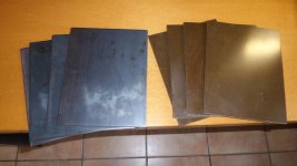
I have in my hands all that is needed...including the bakelite sheets.
Also a lot of my efforts are now on the turntable motor construction...will take some time!
He has had a back surgery and is out of work for a month or so.
I am waiting for him to get better...or i have to look for another CNC shop.
I have in my hands all that is needed...including the bakelite sheets.
Also a lot of my efforts are now on the turntable motor construction...will take some time!
Attachments
- Home
- Loudspeakers
- Planars & Exotics
- My own magnetic planar driver