Let's take a well known mid driver: the Infinity EMIM.
The exposed area is no more than 4.5 cm X 10 cm.
Through the years it has been produced with samarium cobalt and neo magnets (with an increase in output ~4-5db).
However the foil material, dimensions and etching pattern was the same.
One would imagine that a serious manufacturer is working within the limits of his design.
So, when working alone (as a single driver covering just the midrange ~BETA,IRS 1b) it is crossed at 700Hz.
Is there a speaker that had 2 EMIMS?
Yes, the RS 2.5 had them and they cross at 300Hz!
Is there a speaker with 3 EMIMS?
Yes, the RS 2a/2b and they cross at 175 Hz!
With 4?
The RS 4.5 has 4 and the crosspoint is at 150 Hz!
More?
The RS 1b works 6 of them in unison as low-mids (and one purely for midrange) and the cross point is at 125 Hz!
And finally the IRS V has 12 of them and the Xpoint is either 75 Hz(!!!) or according to other sources a healthier 100 Hz.
What is the moral of this story?
In my book it says that you can multiply and get real low...
Some will say that the tuning in each case could be different but i am not at all sure.
Remember that in ALL these speakers the EMIM was working in free air as a dipole.
When loaded with a stuffed chamber behind it, things could have been much better.
If anyone wants to chip in this way of thinking or knows more info i would love to listen...
Last edited:
as i recal it has to do with air load , lowering resonace, but this is for electrostatics, magnepalanars have bit more oempf so im not sure if the same principle aplies, guess it does or less pronounced. further most importend factor is power handling. they can cross lower since power handling inceased by adding them. unless they are all parallel. wich they where not or you would have a verry high efficiency and low power handling.
but for the second part about power handling, it is still a fact that it wont play lower then its own resonance. resonance may drop by adding more elements. but its not a free ticket to whatever low frequency you want to go. if you resonance is lets say 150 you can add panels all you want but you wont get to 50 hz. quads panels have a res of around 70 4 panels stacked they get down to 50. but they are way bigger panels. so and act as baffle as well
but for the second part about power handling, it is still a fact that it wont play lower then its own resonance. resonance may drop by adding more elements. but its not a free ticket to whatever low frequency you want to go. if you resonance is lets say 150 you can add panels all you want but you wont get to 50 hz. quads panels have a res of around 70 4 panels stacked they get down to 50. but they are way bigger panels. so and act as baffle as well
Post #2 and the first part of 3 reflects the issues..
http://www.diyaudio.com/forums/mult...-way-dipole-active-subwoofer.html#post4429882
Maybe one should go a bit bigger than the EMIM?
//
http://www.diyaudio.com/forums/mult...-way-dipole-active-subwoofer.html#post4429882
Maybe one should go a bit bigger than the EMIM?
//
There have been bigger ones.
The Monsoon planar used throughout the VMPS series of speakers has a roughly 1.5 times bigger radiating area.
Usually crossed at 200-220Hz when 4 or 3 where used.
It could go lower but for low power applications.
The Fostex FS21RP was even bigger but a nasty resonance at 650 Hz prevented from using it lower.
The significantly larger LFT-10 breaks up at 125Hz or a bit lower in the neo version.
The european XX-500 (7X11 cm)made by QUADRAL in the '90s was crossed at 400-500 Hz depending on the speaker...could easily reach 250Hz with 24db/oct slope.
I don't like NEO-10. It does not deliver as promised.
I aim at a 17X22-24 cm one with proper openings...a la LFT.
But with a few improvements...
I have heard the Piega 90.2. It was good. But xo is 500Hz. They played loud in a big room. Same driver as in these: http://www.piega.ch/download/Piega-Coax1022-fidelity.pdf
The horizontal pattern of the Neo10 seem good. I'd say keep the width and make it a bit longer for some extra ompfh in the lower region?
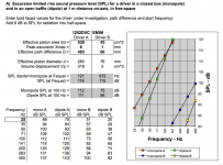
Using this: http://www.linkwitzlab.com/spl_max1.xls gives for EMIM 4,5x10cm and max 1mm (?)- no baffle (D iscenter driver to baffle edge):
The horizontal pattern of the Neo10 seem good. I'd say keep the width and make it a bit longer for some extra ompfh in the lower region?
Using this: http://www.linkwitzlab.com/spl_max1.xls gives for EMIM 4,5x10cm and max 1mm (?)- no baffle (D iscenter driver to baffle edge):
Attachments
I didn't have the dimension specs for this Piega driver.
From the article photos and from careful on screen scale calculations it seems that the true mid element is 14.5 wide to 13 high placed in a roughly 20X22 frame (if someone has the actual specs feel free to correct me).
It is an unusual speaker in many ways...
1) It is wider than it is tall (!) in contrast to the general consensus...remember IRS Gamma?
2) The magnetic force is not symmetrical because it uses bigger magnets in the back!
3) The slits on the back are much smaller...i suspect not only because the rear magnets
are bigger but also to provide the "loading" for the foil...not having to use cloth or any other damping agent (clever, but you can't tamper with it).
That's an interesting calculation about the EMIM.
Proves that all things being equal (400Hz dipole VS 250Hz monopole) you can go roughly an octave lower with the same driver if you work it as a monopole, keeping the SPL in respectable levels...
I will go monopole. I need to cross with a very healthy output (90+ db) at 250Hz max.
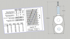
The NEO-10 in a frame of 12.5cm X 25.5cm has a radiating area of 6X20cm.
There is no way to get healthy output at 150 Hz from something so small.
The SPL VS Freq graph that B&G provides looks that there is a hump at 200 Hz and the driver starts to get linear right after 250 Hz @ 83 db....
I will ask for some samples for a 17X22 foil for testing.
The magnets are on their way.
I will talk with a friend who converts my designs into CNC CAD files and we will go on with the steel plates.
I am thinking of asking for two pairs of plastic frames/spacers that will leave the foil with
a maximum displacement of +/- 2.5 and +/- 2mm...(that is ...before hitting the magnets!)
I will have to find a way to tune the foils by applying calculated tension to the frames.
I have some ideas as to how this can be made...to be discussed...
From the article photos and from careful on screen scale calculations it seems that the true mid element is 14.5 wide to 13 high placed in a roughly 20X22 frame (if someone has the actual specs feel free to correct me).
It is an unusual speaker in many ways...
1) It is wider than it is tall (!) in contrast to the general consensus...remember IRS Gamma?
2) The magnetic force is not symmetrical because it uses bigger magnets in the back!
3) The slits on the back are much smaller...i suspect not only because the rear magnets
are bigger but also to provide the "loading" for the foil...not having to use cloth or any other damping agent (clever, but you can't tamper with it).
That's an interesting calculation about the EMIM.
Proves that all things being equal (400Hz dipole VS 250Hz monopole) you can go roughly an octave lower with the same driver if you work it as a monopole, keeping the SPL in respectable levels...
I will go monopole. I need to cross with a very healthy output (90+ db) at 250Hz max.
The NEO-10 in a frame of 12.5cm X 25.5cm has a radiating area of 6X20cm.
There is no way to get healthy output at 150 Hz from something so small.
The SPL VS Freq graph that B&G provides looks that there is a hump at 200 Hz and the driver starts to get linear right after 250 Hz @ 83 db....
I will ask for some samples for a 17X22 foil for testing.
The magnets are on their way.
I will talk with a friend who converts my designs into CNC CAD files and we will go on with the steel plates.
I am thinking of asking for two pairs of plastic frames/spacers that will leave the foil with
a maximum displacement of +/- 2.5 and +/- 2mm...(that is ...before hitting the magnets!)
I will have to find a way to tune the foils by applying calculated tension to the frames.
I have some ideas as to how this can be made...to be discussed...
point 3. my guess is they wanted these bigger magnets on the front as well for better efficiency etc. but did not want to lose the open area at the front. another reason can be that spreading out cavity resonances make them less obvious.
still a very weird decision if you have a pusch pull that is not symmetrical. are they even the same type of magnets >? maybe they used stronger smaller ones in front and weaker /cheaper bigger ones in the back to still have true push pull, and as well skim on the costs, and spread there cavity resonances?
think it would be hard to get it complete symmetrical. ...
witch one is it in the picture>? 30x10 is 300 cm2 dont see it anywhere. also this is about woofers. volume displacement in a membrane is slightly different i think since the sides dont move as much air as the middle part.(or is this why you chose 250cm2) dont know a method to calculate it or something. but i can imagine that the middle part has a xmax of 1mm a pretty big part of the membrane does not. btw is 2mm one way xmax ?
not sure if this model is looking at a pistonic action,
not sure if this model is looking at a pistonic action,
but with strong magnets a 2or maybe even 3mm xmax(one way) is easy obtainable.
i mean i think magnepan used 1.5-2mm with the rubber magnets that peform even worse then normal ferite, and is not push pull either.
try femm maybe you can see the difference between your neo's with xmax of 3 mm versus lowest ferite with xmax of 1.5. see witch one is stronger (neos will be, but how much). ofcourse you have to take in account that the magnepan uses a bigger surface area as well
ooh i could send you a an example, also there is a how to on the forum of FEMM please look at that first
its all complicated in the end")
the strength of magnetic field the current and the weight of the foil all comes to play at how efficient it is. the xmax determ only the maximum spl that could be generated by the membrane as in mechanical limits. chosing to high x max might result in never been able to reach it and lose usfull field strength you could have used.
its all complicated in the end
the strength of magnetic field the current and the weight of the foil all comes to play at how efficient it is. the xmax determ only the maximum spl that could be generated by the membrane as in mechanical limits. chosing to high x max might result in never been able to reach it and lose usfull field strength you could have used.
Last edited:
think it would be hard to get it complete symmetrical. ...
It would be a nearly impossible effort to make a symmetrical magnetic field
using different shape front-back magnets.
The different geometry of the magnet body makes it a nightmare.
I guess they knew that but decided that the other parameters were worth it more.
New data:The Fostex FS21RP midrange (from 650Hz upwards) has an almost
identical frame and radiating surface as the NEO 10...just a little shorter :
(17.2 cm vs 20 cm) but a little wider (6.6 cm vs 6 cm).
The difference in radiating area is minimal 113 vs 120 sq cm.
However the allowance for foil displacement is minimal in the Fostex (about +/- 1mm before hitting the (one piece samarium cobalt) magnets...making it a poor candidate for low mid application.
My resident XX-500s are smaller (7.5 X 11 cm in a frame of 12.5 X 16 cm) but can go easily at sub 400 Hz because they use powerful neo magnets and the foil is allowed a +/- 1.5 mm of travel before hitting the magnets.
I know (!) it as i crank them up often to ear shredding levels.
It is a very accomplished driver (i love them to bits!) but used only in Quadral
VUlkan V and Titan V...
This is more or less the driver i am willing to make.
Some minor alternations will have to be made probably but this is the general idea...
I have withheld some crucial details as i think there will be a commercial interest in this.
Some minor alternations will have to be made probably but this is the general idea...
I have withheld some crucial details as i think there will be a commercial interest in this.
Attachments
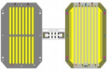
yeah that looks like a planar . you are either using incredible thick metal or you get some bending going . the neo's have struts for strength. the eminim have super thick metal bars. nice trace layout , look like the neo's ? and i like the flange! nice detail
what i got my doubts about is the width of the slots and the width of the traces. i am not sure if you get high/and even enough field in between those magnets to be honest.
they might be to far apart to form a decent field?? lookup femm please. you can moddel the cut out and you know what you got. now its just gambling with money.
magnet open area percentage looks smaller then most designs, thats why i think you should model it maybe
. you are either using incredible thick metal or you get some bending going . the neo's have struts for strength. the eminim have super thick metal bars. nice trace layout , look like the neo's ? and i like the flange! nice detail what i got my doubts about is the width of the slots and the width of the traces. i am not sure if you get high/and even enough field in between those magnets to be honest.
they might be to far apart to form a decent field?? lookup femm please. you can moddel the cut out and you know what you got. now its just gambling with money.
magnet open area percentage looks smaller then most designs, thats why i think you should model it maybe
Last edited:
It's 5mm thick steel plates.
I can go up to N50 magnets...4X4 at the beginning.
I have provision for an external middle reinforcing bar is their strength proves too much.
I have made my comparisons and this looks very promising.
I am willing to make 3-4 prototypes and measure the outcome...
It's going to be a blast!
I can go up to N50 magnets...4X4 at the beginning.
I have provision for an external middle reinforcing bar is their strength proves too much.
I have made my comparisons and this looks very promising.
I am willing to make 3-4 prototypes and measure the outcome...
It's going to be a blast!
- Home
- Loudspeakers
- Planars & Exotics
- My own magnetic planar driver