There is no reason for me to be angry, hence, I am not. I have zero interest in building something like this. However, look around and see how many people bring their ideas here, prototypes, etc. Lots. A few of them, very few, present something they built, they show how nicely it works, but then they help no one to build something similar. It's a community forum, diy. Still, you're welcome here even if you want to keep your schematic hidden. ") No big deal.
No big deal.
No big deal.Well its not a matter of honesty or not , I don't know how many people here are 100% honest and how many are not , including you , and you can't judge people simply like that because you are a moderator or something , and after all you say that you have no interest about something like this or similar .Yeah right. If you wanted to be open about it you would have been . At least be honest about it.
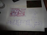
The problem is that this circuit is now under test and by giving and discribe it as idea without many details this may help some people to make it at their own way and even better than me .
We all here because we like electronics and especialy tubes , and we all learn and teach at the same time , by sharing our ideas .
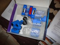
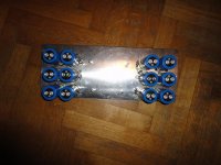
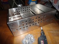
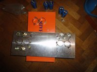
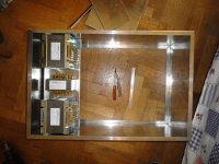
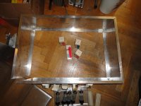
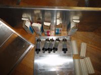
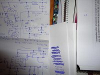
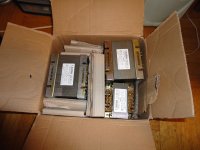
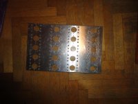
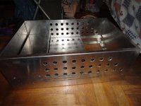
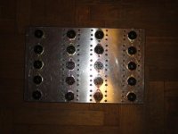
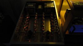
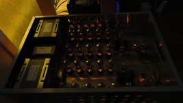
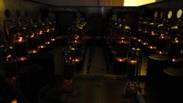
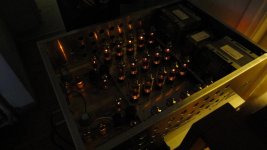
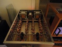
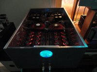
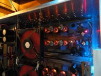
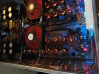
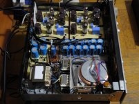
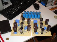
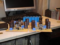
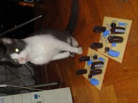
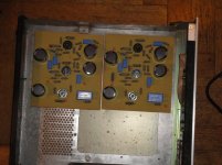
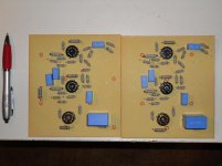
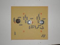
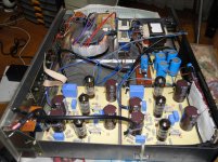
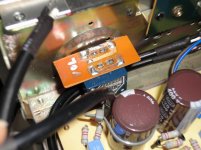
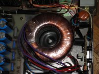
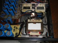
Some fotos during the construction of the amp .
Attachments
-
 DSC00143.JPG213.7 KB · Views: 713
 -
 DSC00170.JPG90.2 KB · Views: 222
 -
 DSC00169.JPG102 KB · Views: 184
 -
 DSC00168.JPG80.3 KB · Views: 163
 -
 DSC00160.JPG204.4 KB · Views: 173
 -
 DSC00157.JPG184.6 KB · Views: 199
 -
 DSC00156.JPG181.9 KB · Views: 634
 -
 DSC00150.JPG101.5 KB · Views: 659
 -
 DSC00147.JPG155.2 KB · Views: 678
 -
 DSC00144.JPG166.4 KB · Views: 669
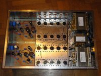
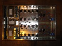
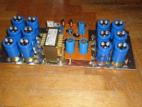
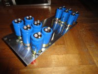
Hi Kevin , thank you very much for your comments . I have discribed the amp in the previous posts , the EF183 is the input and phase splitter tube ( cathodyne type ) followed by two differential gain stages , PCC85 as first stage and the triode sections of the PCL82 as second stage , followed by the drivers ( the pentode sections of PCL82 ) which is cathode followers , driving the 10 PL36 output tubes with AC coupling .The NFB is placed on the cathodes of the two PCC85 . I designed it this way because , I wanted to avoid the use of current source in the cathodes of the first stage , and place the NFB in the cathodes ( like I do ) and not in the grids of the first gain stage for many reasons .All I can is wow..(!!!) Very impressive, and I'm looking forward to seeing more pix, and reading about your project.
Monster amp.
Now you can sale it to us. Atma included.
The bandwidth is amazing!
The aspect so professional
The sense original.
The election in the topology ingeniously.
The changes made for the suggestion of the rest. Faster and reliable.
The money spent economic.
Reliable and efficient is the conclusion.
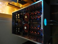
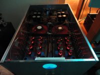
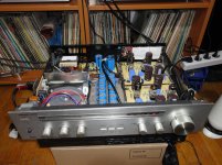
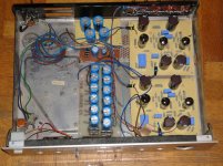
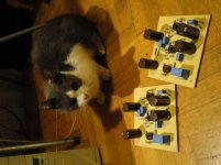
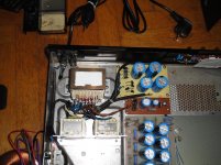
And some fotos of the PL36 Futterman OTL amp .
Now you can sale it to us. Atma included.
The bandwidth is amazing!
The aspect so professional
The sense original.
The election in the topology ingeniously.
The changes made for the suggestion of the rest. Faster and reliable.
The money spent economic.
Reliable and efficient is the conclusion.
Thank you very much for your comments , I appreciate that .
There is two OTL amplifiers presented here , one Circlotron and one Futterman topology , but this thread is related mostly to the Circlotron amp , which later will undergo further improvements , but the Futterman has better frequency response and a little more power and Ι think in the future I will make a reconstruction - improving and will present it in the forum .
Dimitris.
Thank you very much for your comments , I appreciate that .
There is two OTL amplifiers presented here , one Circlotron and one Futterman topology , but this thread is related mostly to the Circlotron amp , which later will undergo further improvements , but the Futterman has better frequency response and a little more power and Ι think in the future I will make a reconstruction - improving and will present it in the forum .
Dimitris.
I think has more damping factor because the futterman has a low impedance but the symmetry and stability of the circlotron is a advantage . We can compensate this with high impedance loudspeakers. Use balanced full is a challenge too. I trying to build one but with AS7 ten per channel, Actually is a Makovski one I got but I decide to change to Atma look. I am attempted for buy a MA60 kit but now i am in bankrupt and my wife is a big factor too.
Congratulations and enjoy your amps and the music that is the end at least more important in this incredible hobby.
Yes the Futterman has lower output impedance due to the interchange of the outputs of the driver stage ( with respect to the output tubes ) it's a variation of futterman topology ( also called Technics variation ) , and the Circlotron has low output impedance too , 1.2Ω measured at 20Vp-p this happens because I use a relatively high proportion of NFB .
And yes the Circlotron have lower distortion as you said due to the nature of it's design that reduce the even harmonics especialy the second harmonic .
As for the economics , we are all in the same difficult situation , Maybe it's more economical to build your amp with your own hands , I am sure that you have the knowledge , but in case you want a help send me a PM .
Good luck
Dimitris .
This is the new partner for my Circlotron OTL , it's my new line preamp , it's called the " Jackal " I gave it this name because it was made with cost saving and intelligently and because it incorporates 3 kinds of feedback , a very small amount of local positive feedback , local negative feedback and global negative feedback .
The gain of the preamp is about 19,4dB ( it's still high and I am thinking to reduce it 3 or 4dB ) , open loop gain is 34dB , global NFB -14,6dB , with very wide frequency response -3dB at 400KHz .
The tubes are 2 PCF200 and 1 EF183 or EF184 on each channel .
Here is some fotos .
The gain of the preamp is about 19,4dB ( it's still high and I am thinking to reduce it 3 or 4dB ) , open loop gain is 34dB , global NFB -14,6dB , with very wide frequency response -3dB at 400KHz .
The tubes are 2 PCF200 and 1 EF183 or EF184 on each channel .
Here is some fotos .
Attachments
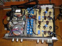
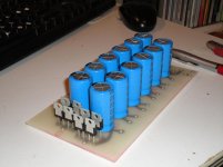
Some fotos during the construction of the preamp .
Attachments
-
 DSC00599.JPG92.9 KB · Views: 207
 -
 DSC00607.JPG143.6 KB · Views: 146
 -
 DSC00608.JPG137.3 KB · Views: 124
 -
 DSC00611.JPG194.3 KB · Views: 163
 -
 DSC00591.JPG134.2 KB · Views: 1,416
 -
 DSC00587.JPG112.8 KB · Views: 126
 -
 DSC00586.JPG116.7 KB · Views: 131
 -
 DSC00580.JPG146.6 KB · Views: 166
 -
 DSC00567.JPG91.8 KB · Views: 629
 -
 DSC00566.JPG70.3 KB · Views: 649
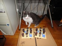
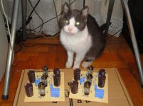
Dady thanks alot , I can build a special one for you if you wantI have a cat like this but I wanna a OTL atma too....
.Thank you a.wayne.Impressive build , on both ........
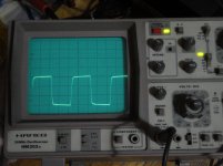
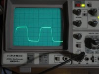
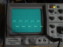
Two weeks ago , I reduce the gain of the preamp , now the gain is 16.7dB with -17,3dB of NFB , the -3db point is "towered" to 500KHZ or above , but I decided to reduce it to 450KHz by raising a little the compensation , now the preamp is sounded cleaner and more accurate with better bass .
Here is some square waves , the first is 50KHZ 3Vp-p , no load
the second is 100KHz 3Vp-p again no load
and the last is 50KHz 2Vp-p onto 1KΩ load .
The output impedance of the preamp surprised me , with 1KHz sine wave 3Vp-p output voltage I place 1KΩ resistor as load and the output voltage droped only 0.1Vp-p , yes yes it's too low , it is only 35Ω .
Attachments
- Home
- Amplifiers
- Tubes / Valves
- My new Circlotron OTL tube power Amp.