Yes , I know that if I connect 16Ω loudspeakers the power will be rised , it is obvious as I see It in the oscilloscope with higher loads I get more peak to peak voltage , my speakers is 8Ω , but I have 4Ω mid-woofer 5 inch 8Ω , and I will connect them in series ( 2 for each speaker ) to get 16Ω , with compensating circuits of course , but this would not happen now .You can double the output power even now running 10 x PL36 triode connected Circlotron only with simple rising of the load(speaker) impedance from 8 to 16 ohm ( or even slightly more, up to 32 ohm ) , this will improve the Amps sonics timbre Significantly to , your Amps will run much cooler to , relative small OTL Amps as yours simple love the higher load(speaker) impedance !
Hi Atmasphere , congratulations for your great amplifiers and thank you for your comment . The PL36 is triode connected with 145 V B+ , 38 - 40 mA for each one, I haven't look at the drivers ( PCL82 ) separately to see what happen , but I suspect them too , I think i will rise a little bit their voltage and i will harden the bias of the triode section a little , because I think the broblem is there .Hi! nice project.
20W at clipping seems like there might be a problem somewhere- I would expect more power with that many tubes.
What is the B+ voltage of the power tubes? Have you looked at the amp with an oscilloscope to see how the driver circuits behave when the amp is clipping?
Yes, I would look at the behavior of the driver circuit, both its output and input. With severe clipping the output tubes should draw so much grid current that your driver will saturate and draw grid current as well. This will saturate the voltage amplifier too.Hi Atmasphere , congratulations for your great amplifiers and thank you for your comment . The PL36 is triode connected with 145 V B+ , 38 - 40 mA for each one, I haven't look at the drivers ( PCL82 ) separately to see what happen , but I suspect them too , I think i will rise a little bit their voltage and i will harden the bias of the triode section a little , because I think the broblem is there .
But with light clipping you should be able to observe the progression of overload in the amp. The question is, is the driver or voltage amplifier saturating before the output section? My guess is that that is the case.
With 10 6AS7s I am used to seeing about 80 to 100 watts into 8 ohms, maybe slightly more, depending on the class of operation. Generally speaking though in an OTL, you want the driver to be capable of pushing the tubes into grid current. If the driver cannot do this you will have overload recovery and maybe also bias control problems.
I would also observe the behavior of the power supplies for the driver. If they start to get noisy as the input signal is increased, then you will have some homework to do
")
The driver stages is two cathode follower ( the pentode sections of the two PCL82 ) driving the output tubes with 2,2 μF capacitors and as I know to drive the tubes in class AB2 ( pushing the tubes into grid current ) its better with DC coupling (of course you know that much better than me ) , but I didn't want this , I mean I don't want too much power , I want to increase it 5 watt more only and I will be happy . As for the 6AS7 each tube have two power triodes , with 13 W plate dissipation for each triode , while the PL36 have plate dissipation 13 W each one , from this is obvious that 10 6SA7 would produce more power than 10 PL36 even if they run in pentode mode , now they run in triode mode . The problem may be as you said in the voltage amplifier ( the triode section of the PCL82 ) that's why I said in the previous post I will rise the voltage of the driver ( the voltage supply is common for the two sections of the PCL82 ) and harden the bias of the triodes by lower the value of the cathode resistor , and I think this will be a good improovement ( the gain will increased too ) , of course I have to observe the supply voltage not to fall when the input signal is increased , thanks .Yes, I would look at the behavior of the driver circuit, both its output and input. With severe clipping the output tubes should draw so much grid current that your driver will saturate and draw grid current as well. This will saturate the voltage amplifier too.
But with light clipping you should be able to observe the progression of overload in the amp. The question is, is the driver or voltage amplifier saturating before the output section? My guess is that that is the case.
With 10 6AS7s I am used to seeing about 80 to 100 watts into 8 ohms, maybe slightly more, depending on the class of operation. Generally speaking though in an OTL, you want the driver to be capable of pushing the tubes into grid current. If the driver cannot do this you will have overload recovery and maybe also bias control problems.
I would also observe the behavior of the power supplies for the driver. If they start to get noisy as the input signal is increased, then you will have some homework to do
Hi Dimitris, just to mention something about PCL82, it's triode section is pretty much useless - it is way to sensitive for overloading.
I had big problems in getting right sound until I used standard ECC81/83 tube instead of triode section from PCL82 - then you get to hear what PCL82 sounds like...at least in SE amplifier.
Max
I had big problems in getting right sound until I used standard ECC81/83 tube instead of triode section from PCL82 - then you get to hear what PCL82 sounds like...at least in SE amplifier.
Max
Trouble I found with cap coupling to the O/P tubes, you'll never really be able to drive the grids positive very much, as the caps charge and give blocking-distortions...
A Cathode-follower can be DC coupled to the grids of O/P valves, the CF grid voltage used to set bias on the O/P valves, its tail tied to a suitable negative supply.
--While not totally perfect its a bit better than using a cap After the CF to drive the O/P tubes....
--A MOSFET follower is a better alternative to the standard CF, but many guys dont like sand, although used in this way are completely transparant, --and dont need heaters either!
Trouble I found with cap coupling to the O/P tubes, you'll never really be able to drive the grids positive very much, as the caps charge and give blocking-distortions...
A Cathode-follower can be DC coupled to the grids of O/P valves, the CF grid voltage used to set bias on the O/P valves, its tail tied to a suitable negative supply.
--While not totally perfect its a bit better than using a cap After the CF to drive the O/P tubes....
--A MOSFET follower is a better alternative to the standard CF, but many guys dont like sand, although used in this way are completely transparant, --and dont need heaters either!
This is similar to my own findings. IMO you can't really build a successful OTL until the driver is direct-coupled to the power tubes. The blocking distortion is an obvious point, but you also run into problems with overload recovery or bias drift (if fixed bias is employed), loss of bass bandwidth and impact, or all three!
These problems are neatly solved with a direct-coupled driver. It also means the power output will now be limited by the output tubes rather than the driver, and the significance of that is you will have a smoother overload sound as you will get less odd-ordered harmonics as the amp nears saturation. This means the amp will sound smoother but you will not loose any detail!
The direct-coupled driver also allows you to use a smaller coupling cap to drive it, so you have a wider range of good coupling caps to choose from, as a smaller cap will have less coloration and greater detail.
Hi Max , I think the triode section of the PCL82 is not so useless as you say , I have many of them and I decide to use them in the amp , I think this triode is the reason for decreasing the high frequency response of the amp , but it's still high 170Khz -3dB in comparing with the 195 Khz -3dB of the Futterman PL36 amp . But it sounds good with detailed sound and better bass than the Futterman , so I think I will leave it as it is . As for the overloading I will bias it a litlle bit harder as I say before and I will see what happen , BTW before I choose this tube ( PCL82 ) I was searching for the PCL200 ( it has more powerful triode section ) but I didn't find it easy as I found the PCL82 .Hi Dimitris, just to mention something about PCL82, it's triode section is pretty much useless - it is way to sensitive for overloading.
I had big problems in getting right sound until I used standard ECC81/83 tube instead of triode section from PCL82 - then you get to hear what PCL82 sounds like...at least in SE amplifier.
Max
I know that , I didn't say that I want to drive the grids of the output tubes positive with AC coupling , I say it is better with direct coupling , for many reasons ( with direct coupling the output tubes will maintain it's correct biasing even if they driven harder because of the lack of any additional non linear resistive component like capacitors ) , but for now I don't think of that at all , maby in the future I will do it , and of course I know the way .Trouble I found with cap coupling to the O/P tubes, you'll never really be able to drive the grids positive very much, as the caps charge and give blocking-distortions...
A Cathode-follower can be DC coupled to the grids of O/P valves, the CF grid voltage used to set bias on the O/P valves, its tail tied to a suitable negative supply.
--While not totally perfect its a bit better than using a cap After the CF to drive the O/P tubes....
--A MOSFET follower is a better alternative to the standard CF, but many guys dont like sand, although used in this way are completely transparant, --and dont need heaters either!
Thank you Atmasphere - Ralph for this extra information , I will try it in the future as I said , but how much power you think that I can get now with AC coupling and the PL36 tube triode connected , with no clipping of the triode section of the PCL82 and with no noisy power supply for it and for the cathode follower .This is similar to my own findings. IMO you can't really build a successful OTL until the driver is direct-coupled to the power tubes. The blocking distortion is an obvious point, but you also run into problems with overload recovery or bias drift (if fixed bias is employed), loss of bass bandwidth and impact, or all three!
These problems are neatly solved with a direct-coupled driver. It also means the power output will now be limited by the output tubes rather than the driver, and the significance of that is you will have a smoother overload sound as you will get less odd-ordered harmonics as the amp nears saturation. This means the amp will sound smoother but you will not loose any detail!
The direct-coupled driver also allows you to use a smaller coupling cap to drive it, so you have a wider range of good coupling caps to choose from, as a smaller cap will have less coloration and greater detail.
But most of the Futterman topology OTL amps use capacitors coupling , and some of them sounds great .. IMO you can't really build a successful OTL until the driver is direct-coupled to the power tube .
Aye, Mine with its, As you say, --'Non linear resistive capacitors' sounds superb--
Even if it IS only 4W RMS!--Slightly off topic, but replacing my cathode-resistors with a CVS didnt improve the power much, Maybe a watt or two, My issue is similar to yours, Insufficient Drive and insufficient +-B volts....
--Still, I'm merely using 2 PL509 to achieve this, Guess I could get easily 12W RMS by doubling up O/P valves....
As I said before the problem of your amp is in the PI itself , and not in the AC coupling ( most of Futterman amps use capacitors coupling ) , and I said that is better to turn it in fixed bias . While my amp delivers 20 W into 8 Ω load , and this is not a very big problem , I will try to improve it in the weekend and I will came with the results , and I don't suspect the drivers or the Ac coupling too much as I suspect the triode section of the PCL82 . BTW 10 PL36 is equal to 4 PL509 in currents and plate dissipation .Aye, Mine with its, As you say, --'Non linear resistive capacitors' sounds superb--
Even if it IS only 4W RMS!--Slightly off topic, but replacing my cathode-resistors with a CVS didnt improve the power much, Maybe a watt or two, My issue is similar to yours, Insufficient Drive and insufficient +-B volts....
--Still, I'm merely using 2 PL509 to achieve this, Guess I could get easily 12W RMS by doubling up O/P valves....
looking at the PL36 curves, Looks like more like half a PL509...
It allegedly can pass some 700mA at 200V plate,--Obviously in 'pulse' just as the '509 is rated at 1.4A in the same scenario.....
--Plate dissipation isnt so much the issue for an OTL, rather the capabilities for Cathode-Current....
I agree, I have limitations with my PI currently, but running fixed-bias Isnt going to fix the PI issue.
--Everyone does Fixed-Bias for OTL's, I like doing things not done/tried before, I was told early on by a friend, it wouldn't work At All--Proved That wrong!....
Anyway, I digress, without a schematic of your amp to refer to, its rather difficult to say just why the expected power from 10 PL36 is rather low, Looking at their spec, I should have thought that 100W would have been closer to the level they are capable of, maybe more if you want to screw 'em....
Just Wish I had a pair of PL36 to try in my amp--Be interesting to compare O/P powers, but I sold the last 10 I had some years ago. Best I could sub it for would be the PL504 which has sorta similar ratings....
The PL36 has 200mA max cathode current and 700mA peaks ( so its a litlle bit smaller than half PL509 ) in pulse as you said , but the plate dissipation tell as a lot about the cathode current especialy in sweep tubes . You seem to misunderstand all that I say , of course the fixed bias don't solve the problems of the PI , and a little quiz ( I speek to you freindly I only wanna help and without any misunderstanding ) - Why do I insist so much about the fixed bias ? which important parameter of the OTL amp affected by the auto bias ? think well and tell me . You overestimated the power of the 10 PL36 by saying 100W ( its not 10 6AS7 ) , even if the 10 runs in pentode mode , and if they run in pentode they would give about 52 - 55W and in triode mode the maximal is about 26-28W ( now they run in triode mode ) , and you consider 12W from 2 PL509 enough ? I think you making a big mistake here . BTW with 2 6C33C you get 25W , and I think with two PL509 you get near 22W in pentode mode .looking at the PL36 curves, Looks like more like half a PL509...
It allegedly can pass some 700mA at 200V plate,--Obviously in 'pulse' just as the '509 is rated at 1.4A in the same scenario.....
--Plate dissipation isnt so much the issue for an OTL, rather the capabilities for Cathode-Current....
I agree, I have limitations with my PI currently, but running fixed-bias Isnt going to fix the PI issue.
--Everyone does Fixed-Bias for OTL's, I like doing things not done/tried before, I was told early on by a friend, it wouldn't work At All--Proved That wrong!....
Anyway, I digress, without a schematic of your amp to refer to, its rather difficult to say just why the expected power from 10 PL36 is rather low, Looking at their spec, I should have thought that 100W would have been closer to the level they are capable of, maybe more if you want to screw 'em....
Just Wish I had a pair of PL36 to try in my amp--Be interesting to compare O/P powers, but I sold the last 10 I had some years ago. Best I could sub it for would be the PL504 which has sorta similar ratings....
Last edited:
Well, The 'Fixed Bias, Self-Bias' issue was a choice as Ive not seen it done before, a friend told me it Wouldt work At All, but since proved him wrong.
Yes--I agree, its 'lossy' of consumed power--But arn't ALL OTL's power hungry--Especially those with 6C33c, with those Huge heaters!
The idea was to produce a Low Power OTL, that is easy to construct, has a simple PSU not needing O/P Bias-supplies and the attendant constant issues of bias-drift associated with 6C33C etc, and constant need to check/adjust bias. (Not that this is a probem with 6C33C IMHE)
Currently, as I'm losing around 25V across the cathode-resistors, I am well below the 160V needed to drag 1.4A through a PL509, I only have 125V across the tube itself.
--Yes, Go fixed bias, I have nearly enough volts, but that wasnt the design goal, but certainly would increase power.
Today, I hope to overwind the transformer to give me 190V +-B volts and will re-test, I'll have plenty of headroom for the PL's then.--Its a large 600VA Toroid, originally gave two 55V supplies, but Ive shall we say--Modified it!
So, Why Self-Bias?--Because its Different from the hurd, Ive not seen it done before in OTL, and results so far are pretty good...
(After all, Everyone does Fixed bias,--nothing new there!)
As to increasing the power--Easy, Double up on O/P valves, But I'm looking to get the best out of just 2 first. Currently with a MOSFET in place of cathode resistor, I'm up to 5.3W, Not bad for something some consider wouldn't work at all!
BTW Yes, easy to get 25W from a pair of 6C33c, --Its also possible to get 56W from the same pair in Circlotron running 200V rails,--I did it!----This was based on the 'Sweep-Tube' circlotron monoblock, and modded for the 6C33C....
The Allan Kimmel 'sweep-tube' Circlotron using 4 PL509 will generate 115W into 8 ohms, at 180V rails, and 210W running 8....
Here's an article on it--Interesting reading--
Sweep Tube OTL Monoblock © 2004 Alan Kimmel
You are probably not that far off the mark right now. Do you have plans of posting the circuit you are using?Thank you Atmasphere - Ralph for this extra information , I will try it in the future as I said , but how much power you think that I can get now with AC coupling and the PL36 tube triode connected , with no clipping of the triode section of the PCL82 and with no noisy power supply for it and for the cathode follower .
OK , the self bias is your choice , but you want to increase the power , and as you say you want to get the best results from the two valves , all this is good , but have you measure the output impedance of your amp ? Ths is the answer to the quiz , the self -bias increase the Zout of the amp ( the reason is obvious ) , and when you drive 8ohm loads the results is low power , if you try to drive 16 ohm load you will see significent power increasing .Well, The 'Fixed Bias, Self-Bias' issue was a choice as Ive not seen it done before, a friend told me it Wouldt work At All, but since proved him wrong.
Yes--I agree, its 'lossy' of consumed power--But arn't ALL OTL's power hungry--Especially those with 6C33c, with those Huge heaters!
The idea was to produce a Low Power OTL, that is easy to construct, has a simple PSU not needing O/P Bias-supplies and the attendant constant issues of bias-drift associated with 6C33C etc, and constant need to check/adjust bias. (Not that this is a probem with 6C33C IMHE)
Currently, as I'm losing around 25V across the cathode-resistors, I am well below the 160V needed to drag 1.4A through a PL509, I only have 125V across the tube itself.
--Yes, Go fixed bias, I have nearly enough volts, but that wasnt the design goal, but certainly would increase power.
Today, I hope to overwind the transformer to give me 190V +-B volts and will re-test, I'll have plenty of headroom for the PL's then.--Its a large 600VA Toroid, originally gave two 55V supplies, but Ive shall we say--Modified it!
So, Why Self-Bias?--Because its Different from the hurd, Ive not seen it done before in OTL, and results so far are pretty good...
(After all, Everyone does Fixed bias,--nothing new there!)
As to increasing the power--Easy, Double up on O/P valves, But I'm looking to get the best out of just 2 first. Currently with a MOSFET in place of cathode resistor, I'm up to 5.3W, Not bad for something some consider wouldn't work at all!
BTW Yes, easy to get 25W from a pair of 6C33c, --Its also possible to get 56W from the same pair in Circlotron running 200V rails,--I did it!----This was based on the 'Sweep-Tube' circlotron monoblock, and modded for the 6C33C....
The Allan Kimmel 'sweep-tube' Circlotron using 4 PL509 will generate 115W into 8 ohms, at 180V rails, and 210W running 8....
Here's an article on it--Interesting reading--
Sweep Tube OTL Monoblock © 2004 Alan Kimmel
I will make some modifications in the weekend and I will see how it goes . The circuit is designed by me , and its an experimental , and maby in time I will post it .You are probably not that far off the mark right now. Do you have plans of posting the circuit you are using?
- Home
- Amplifiers
- Tubes / Valves
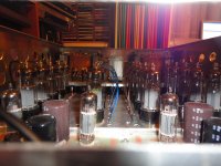
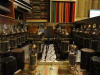
- My new Circlotron OTL tube power Amp.