Joel,
AFAIK you can use Exicon output devices, as the original Renesas ones are obsolete.
https://www.diyaudio.com/community/...esigned-for-music.119151/page-67#post-7189329
AFAIK you can use Exicon output devices, as the original Renesas ones are obsolete.
https://www.diyaudio.com/community/...esigned-for-music.119151/page-67#post-7189329
Last edited:
Profusion (UK) are the usual source for the Exicon Mosfets & I don't think they have a USA / Canada distributor:
https://www.profusionplc.com/type/lateral-mosfet
https://www.profusionplc.com/type/lateral-mosfet
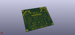
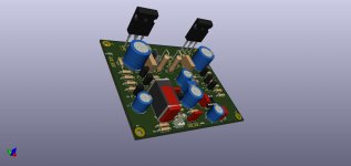
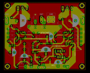
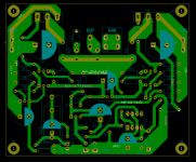
He modificado la pcb para poder usar mosfet exicons TO-3P/TO_247.
También eliminé los rastros en la cara frontal para dejar una sola capa de cobre plano a tierra gnd en la cara superior.
Úsalo como quieras o modifícalo, quería contribuir gratis...
También eliminé los rastros en la cara frontal para dejar una sola capa de cobre plano a tierra gnd en la cara superior.
Úsalo como quieras o modifícalo, quería contribuir gratis...
Attachments
Last edited:
The little brothers are also active and in stock:Incluso en Profusion el ECX10xxx está agotado
ECW20P20 20N20 todavía están act
ECW10P20
ECW10N20
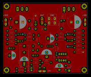
I have modified the pcb to be able to use mosfet exicons TO-3P/TO_247.He modificado la pcb para poder usar mosfet exicons TO-3P/TO_247.
También eliminé los rastros en la cara frontal para dejar una sola capa de cobre plano a tierra gnd en la cara superior.
Úsalo como quieras o modifícalo, quería contribuir gratis...
I also removed the traces on the front face to leave a single layer of flat copper to ground gnd on the top face.
Use it however you want or modify it, I wanted to contribute for free...
Sorry for the lenguage
There is a bug on my pcb! . The exicons mosfets are GSD pins (1, 2 and 3) and I misplaced them and confused with the previous schematic of Hitachi to-3 metallic 2sj /2sK GDS mosfets.
Mr. Administration, let me delete my previous messages and post the correction as soon as possible, thanks!
Mr. Administration, let me delete my previous messages and post the correction as soon as possible, thanks!
Mr. Administration,

Oh I'm not so sure we have one of those
")
There are lots who follow or watch threads silently and so we make it a rule that we don't edit or delete material for technical inaccuracies
Quote your post along with any corrections and that way everyone following knows the timeline and what is happening.
Hi Karl,
I have a few questions/comments on the design:
Input Impedance
You have indicated that the input impedance is 33kΩ and is set by R2. Wouldn't the input impedance be set by R1 & R2 in parallel for a value of 13.2KΩ? Also, is R1 necessary if R2 is seen by the source as connected to ground? I notice that Rod Elliott's Project 12 design, which has a similar input stage, only has the equivalent of your R2.
Output Inductor
You've mentioned that this amplifier is very stable and the output inductor may not be needed. I did some reading in Douglas Self's book (page 363 of the 6th edition) where he mentions that a series resistor as low as 0.1Ω in the output will dampen ringing in the same fashion as an output inductor, at the expense of a drop in maximum output power and dampening factor. If this is correct, it would seem the output inductor is not necessary (as you have speculated).
Output Resistors
You've mentioned that since this amp has a lateral MOSFET output stage, the 0.22Ω output resistors R23 & R24 may not be needed or might be OK at a lower value. In simulations, if I reduce these from 0.22Ω to 0.1Ω, I need to also reduce the feedback resistors R19 and R20 from 220Ω to 100Ω. Does this make sense to you? With these values, the current through the drivers remains the same.
Note: my interest in lower values is due to suggestions by Douglas Self that lower values result in lower order harmonics (page 277 of the 6th edition), and that 0.1Ω should be sufficient for thermal stability. Simulations seem to support this.
Bias Spreader & Servo Caps
Is the value for the bias spreader cap C6 (22μF )and servo cap C5 (10μF) critical? I'm assuming they're not and a builder could use 47μF all around (the same as cap C4) to make ordering easier.
Output Devices
The design is spec'd with ±45V rails. If Exicons double-die TO-264 devices are used (ECW20N20 & ECW20P20), I believe the rails could be raised a bit. If these are used, I think the limiting factor becomes the Q3 and Q5 TO-92 devices. Based on my simulations, I think that ±49V (from a 35-0-35) is safe. Anything beyond this and the dissipation through the Q3 and Q5 TO-92 devices reaches or exceeds their limits. Also, the double-die devices have a higher input capacitance. As a result, the gate stoppers R18 and R21 may need to be lowered. No question here - just my observations.
Yes, the input impedance would be the combined value of those two resistors
The 33k essentially sets the basic input impedance and is considered an integral part of the amp. The resistor on the other side of the cap is more 'user choosable' and in the case of an integrated amp could be just the volume control. Its worth mentioning that the lowish input impedance lends itself to use of a linear pot rather than a log with R1 being scaled to suit the pot value.
Output inductors aren't really detrimental in any way and they do provide an additional layer of safety. If the layout and construction of the amp is good then it almost certainly would be fine without the inductor as long as the 0.22 ohm series output R of the original was preserved.
Thermal stability has never been an issue and the design went for the simple option of relying on the intrinsic negative tempco of the laterals. That won't change whatever you do with the 0.22's
There are some aspects of the design I would probably do differently now than all those years ago when this was first developed. What I would say is that I would be wary of changing things without fully evaluating the changes in a real build... that can be a real trap, one I've fallen into several times over the years. What seem obvious tweaks and improvements to a tested and worked design can sometimes throw up other unexpected issues.
That's not to say you shouldn't try these things, just that they need proper evaluation.
The bias spreader cap will be fine, the cap in the servo probably OK and again I say that because it is an untried change. It will alter the risetime of the -12 volt rail to the TL071. Almost certainly OK but it is untested.
Higher rails I would not advise. You gain nothing in terms of subjective output and as you say it pushes the dissipation of the T092 ever higher, I would say too high. They run hot and as it stands have proved 100% reliable over all these years.
Thanks for interest
It is worth mentioning that the input impedance is determined mainly by the 33k and that is quite low in the scheme of things. If you are feeding the amp directly from a pot wiper (volume control) then you also have the effect of the 150pF cap forming a low pass filter. If the pot is high in value such as 47k or 100k then that will begin to cause some HF roll off.
The 33k essentially sets the basic input impedance and is considered an integral part of the amp. The resistor on the other side of the cap is more 'user choosable' and in the case of an integrated amp could be just the volume control. Its worth mentioning that the lowish input impedance lends itself to use of a linear pot rather than a log with R1 being scaled to suit the pot value.
Output inductors aren't really detrimental in any way and they do provide an additional layer of safety. If the layout and construction of the amp is good then it almost certainly would be fine without the inductor as long as the 0.22 ohm series output R of the original was preserved.
Thermal stability has never been an issue and the design went for the simple option of relying on the intrinsic negative tempco of the laterals. That won't change whatever you do with the 0.22's
You've mentioned that since this amp has a lateral MOSFET output stage, the 0.22Ω output resistors R23 & R24 may not be needed or might be OK at a lower value. In simulations, if I reduce these from 0.22Ω to 0.1Ω, I need to also reduce the feedback resistors R19 and R20 from 220Ω to 100Ω. Does this make sense to you? With these values, the current through the drivers remains the same.
Note: my interest in lower values is due to suggestions by Douglas Self that lower values result in lower order harmonics (page 277 of the 6th edition), and that 0.1Ω should be sufficient for thermal stability. Simulations seem to support this.
There are some aspects of the design I would probably do differently now than all those years ago when this was first developed. What I would say is that I would be wary of changing things without fully evaluating the changes in a real build... that can be a real trap, one I've fallen into several times over the years. What seem obvious tweaks and improvements to a tested and worked design can sometimes throw up other unexpected issues.
That's not to say you shouldn't try these things, just that they need proper evaluation.
Is the value for the bias spreader cap C6 (22μF )and servo cap C5 (10μF) critical?
The bias spreader cap will be fine, the cap in the servo probably OK and again I say that because it is an untried change. It will alter the risetime of the -12 volt rail to the TL071. Almost certainly OK but it is untested.
Again I'm going to say that all these things change the basic design of the amp. The double die's have been used and with no issues and the input capacitance is low enough to not be an issue to the driver stages.The design is spec'd with ±45V rails. If Exicons double-die TO-264 devices are used (ECW20N20 & ECW20P20), I believe the rails could be raised a bit. If these are used, I think the limiting factor becomes the Q3 and Q5 TO-92 devices.
Higher rails I would not advise. You gain nothing in terms of subjective output and as you say it pushes the dissipation of the T092 ever higher, I would say too high. They run hot and as it stands have proved 100% reliable over all these years.
Thanks for interest
32 volts would get you around 45 volts dc but remember at low loading the regulation % value of the transformer will make that higher. A 30-0-30 or even 28-0-28 is probably more suitable. You are looking at around 6 to 8% regulation figure for transformers in the 300va to 160va range. Then you have the tolerance on mains voltage. A 230 vac primary can easily see 240 to 245 volts in the UK.
Thanks for the help Mooly! Looking forward to building this.
I plan on using a 500VA transformer with 30V secondaries from Avel Lindberg and TO-247 Exicon devices. I figure this give me a bit of a safety margin with dissipation in the TO-92 without sacrificing much. I don't listen at loud levels. Plus, I already have the transformer and a stack of Exicon devices.
I plan on using a 500VA transformer with 30V secondaries from Avel Lindberg and TO-247 Exicon devices. I figure this give me a bit of a safety margin with dissipation in the TO-92 without sacrificing much. I don't listen at loud levels. Plus, I already have the transformer and a stack of Exicon devices.
500VA is plenty, I doubt you will come close to needing that and the voltage sounds perfect.
(As for the FET's, well the original single die devices (in a T03 outline) were used in some very popular amps such as the Maplin LatFet and the specs of that were 100wrms into 8 ohm and 150wrms into 4 ohm as an absolute max on -/+55 volt rails)
and the voltage sounds perfect. (As for the FET's, well the original single die devices (in a T03 outline) were used in some very popular amps such as the Maplin LatFet and the specs of that were 100wrms into 8 ohm and 150wrms into 4 ohm as an absolute max on -/+55 volt rails)
- Home
- Amplifiers
- Solid State
- My MOSFET amplifier designed for music