Nothing much in detail beyond real world testing early on with 82db/W speakers and driving these just about up to clipping point as monitored on a scope. The levels are just so far above anything I would ever use at home that I consider clipping part of the performance envelope that will never be entered in normal use. Ultimately if you reach the clip point then you need a bigger amp (running on higher rails) and that applies to any design.
Fwiw simulation of the amp shows clipping to be well behaved.
Approx 0.8 volts peak is needed to reach clipping. This shows 1 volt peak applied and then 4 volts peak applied.
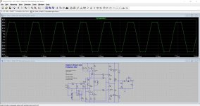
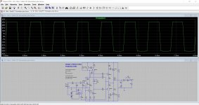
Fwiw simulation of the amp shows clipping to be well behaved.
Approx 0.8 volts peak is needed to reach clipping. This shows 1 volt peak applied and then 4 volts peak applied.


Hi Mooly
I have a very good day with your nice power amp. I made the buffer with a filter RC (2kOhm, 330pF) this limiting the input frequencies at around 240kHz.
To verify that all was OK, after having checked that the output of the buffer did what it should do with the frequency generator, and being a bit afraid to use the LM3562 (I bought a few of them at Mouser, they are expensive as you already know), I did put an TL072 instead for the first try.
The result was so bad that I thought I had killed the sound of your amplifier. I did put a CD of Decca, it is Sinfonietta from Leos Janacek. I do like this music a lot, and I know it very good.
Then I have decided to put the LM3562. What a huge difference ! The power amp was singing again as it did before with Sinfonietta from Janacek when no buffer was connected.
After that, for pleasure, I did put the violin concerto of Mendelssohn played by Maxim Vengerov, a Teldec CD. Wonderful, really wonderful ! Then for being very happy for the rest of the day I did put His Majesty's Harper (Andrew Lawrence-King) a CD of DHM (Deutsche Harmonia Mundi), He is playing right now music from Dowland, William Byrd and others. A Master ! Fantastic !
Now I have no pleasure to report that the TL072 sound bad as a buffer with your amp, but this is the truth. I don't understand why it is so. The TL072 is a good op amp.
Well I will again write to you 'Thank You Mooly' for this so good sounding power amplifier.
Have a good end of this day Mooly.
Best regards
rephil
Well that's goodI have a very good day with your nice power amp.
Pleased you are enjoying the amp though.
Hi Mooly
I rate very high the TL072 too. I have forgotten when I did buy these TL072 I have home, but it is a big lot of years. This TL072 was made by SGS Thomson. I have the Texas Instrument TL072 also, but I see no interest in trying one as I have now no problem. There is a 120 Ohm resistor in series at each output ...
Thr LM4562 did the job, so no problem even if I don't understand why a TL072 sounded so bad in the high frequencies.
Best regards
rephil
Yes indeedThere is a 120 Ohm resistor in series at each output ...
When we wrap feedback around the chip we automatically include that resistor in the loop and the output impedance at the chip output pin effectively becomes only a fraction of an ohm. If that wasn't the case we would see the output level drop as we load the chip but it doesn't, it holds up because the effective output impedance is so low because of where we take the feedback from. The signal level at the other end of the 120 ohm (that we can not get at) will increase as the chip is loaded.
That resistance and the effect of load capacitance can cause instability if it alters the phase margin enough although I've never actually experienced it myself with the TL0 series.
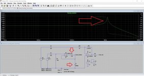
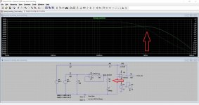
Here is an opamp buffer with 120 ohms added and then capacitively loaded. It doesn't look good. Just look at the left hand opamp... it was a circuit from something else.
Now we add just 47 ohms series resistance but crucially that 47 ohm is now 'outside' the feedback loop, however the 47 ohm and the load capacitance together do in fact modify the feedback network and now adds a 'zero' into the feedback transfer. Now the response is much tamer and stability greatly improved.
Last edited:
Yes indeedThe 120 ohm is internal to the chip and is really the open loop output resistance of the opamp.
When we wrap feedback around the chip we automatically include that resistor in the loop and the output impedance at the chip output pin effectively becomes only a fraction of an ohm. If that wasn't the case we would see the output level drop as we load the chip but it doesn't, it holds up because the effective output impedance is so low because of where we take the feedback from. The signal level at the other end of the 120 ohm (that we can not get at) will increase as the chip is loaded.
That resistance and the effect of load capacitance can cause instability if it alters the phase margin enough although I've never actually experienced it myself with the TL0 series.
Here is an opamp buffer with 120 ohms added and then capacitively loaded. It doesn't look good. Just look at the left hand opamp... it was a circuit from something else.
Now we add just 47 ohms series resistance but crucially that 47 ohm is now 'outside' the feedback loop, however the 47 ohm and the load capacitance together do in fact modify the feedback network and now adds a 'zero' into the feedback transfer. Now the response is much tamer and stability greatly improved.
View attachment 1071626
View attachment 1071627
Hi Mpply
Thank you for your answer. I have on my bench very short wires connecting the buffer to the power amp input, a few cms, so 5nF eems much.
What I wrote is that I did add a physical external 120 Ohm resistor in series to the output chip. This resistor is not connected into the loop of the follower, it is outside the feedback loop. I have of course a small gain loss, I have choosen it to be around 1%. Sorry that my English is a bit weak.
Interesting simulations Mooly. Thank you.
Best regards
rephil
Your English is fine
I really don't know why it sounded so bad then. I do genuinely regard these as very good sounding...
Dunno.
Hi Mooly
Thank you for your kind words about my English.
I did check several op amps this morning. Here it is : the OP072CP from ST, TI, and the AD712JN.
I have no doubt about what I am hearing using the CD Sinfonietta (Leos Janacek). This CD is hard to get singing good in the speakers, as there are many trumpets and many drums too playing very loud. All sound not so good to me, mostly the same as the TL072CP from ST. But bad at my hears don't mean they should be thrown away, I regard these op amp as really good sounding too ! It is that the LM4562 sounds better here in my lab with your nice power amp, and it is exactly the sound I want to get.
The small loss of gain that I spoke about ( I have it around 1% ) is the fact of the input filter. I checked it early using the function generator. The wires I did use between buffer and the power amp are for connecting microphones, so a few pF / meter, and less than 50cm cannot be at the end 5nF.
Now I have connected and good working in my lab all what I will put in the chassis. I did not yet evaluate the goodness of the bias as the small heatsinks I do use are not the one I will get in the chassis. They are bigger, and the thermal stability of the heatsink is not at all the same, I might eventually even going up or lower with the mV between the drains ! At first, I will put the power amps on the heatsinks of the chassis they will really get. For the time I did put 60mV between the two 0.22Ohm and it is very good sounding for hours.
Best regards
rephil
Around a 100ma is generally considered optimal for a pair of lateral FET's, 200ma if you are using the double die 16 amp devices simply because that is the point where the temperature coefficients coincide and the current at its most stable as the FET's heat and cool.
The amp deliberately does not use any form of temperature compensated vbe (or vgs) multiplier like most conventional amps and this amp just uses a single resistor to set the bias current. This was the standard way of doing it with laterals. It works really well and keeps the circuitry simple but if you want to go higher then you can.
I settled on the LM4562 after trying a few types and listening to them for a few months. I also tried some of the OPA2134 series (I didn't like those at all) and the OPA2604 which is another favourite (no longer available though)
Hi Mooly
Thank you for your explanation about the resistor that sets the bias current. I am an honest man and as you understand it not an EE. LOL, I could not resist to this one ... But don't understand what I don't think and what I did not write !
It is a good day, the temperature in my lab is acceptable, so I could try a few others op amp I have home.
Here it is :
The LME49720 sounds equally good as the LM4562 (the datasheet seems to be the same thing too). I hear no difference in my speakers.
The NE5532A, sounds good too, but with less detailed sound. It is a good sounding op amp.
The OPA2134 sounds also good, but a bit more like the TL072CP, even if it is a better op amp, this sound wise. I still prefer the LM4562, this is the one I prefer from all I did try.
I did not speak of the stereo effect because I cannot use the speakers in my lab for this test : they are placed above others speakers (two Pioneer CS-767) that I use connected to a radio. When I sit at the PC, the connected speakers to your power amp are placed above my head ... Not very distant. So I will report my impressions when the power amp will be in its chassis later on, and connected at my Canton good speakers, not in my lab.
In all, people cannot be wrong connecting a buffer using a LM4562, NE5532A, OPA2134, LME49720. The best in my lab being the LM4562, but the differences are really very small, and more an opinion about what I did hear than facts.
Have a nice day Mooly
Best regards
rephil
That should be very similar to the 4562 I think.The NE5532A, sounds good too, but with less detailed sound. It is a good sounding op amp.
It is worth mentioning that the input impedance is determined mainly by the 33k and that is quite low in the scheme of things. If you are feeding the amp directly from a pot wiper (volume control) then you also have the effect of the 150pF cap forming a low pass filter. If the pot is high in value such as 47k or 100k then that will begin to cause some HF roll off.
I used a 10k motorised ALPS pot in mine with a very low gain 'preamp'. The main reason for me using a 'preamp' was to configure the input switching around an inverting opamp stage. This also gave the opportunity to easily set individual gains for each input so that they all sources sound at the same level subjectively.
I found the power amp was totally stable even without the 150pF cap and so at you own risk
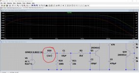
The image shows the response of the input filter (the 150pF) when fed from a source of 5k, 10k and then 22k impedance. As the source impedance increase the HF roll off occurs earlier. So if you are feeding the amp from say a 47k pot then you will start to get some HF rolloff.
A good question actually because the gain of the power amp is higher then most at around 34db. For most modern signal sources you shouldn't need any extra gain.Why you need a buffer?
Another idea for a buffer is to use a simple discrete transistor one. It doesn't always have to be an opamp.
Thanks Mooly.That should be very similar to the 4562 I think.
It is worth mentioning that the input impedance is determined mainly by the 33k and that is quite low in the scheme of things. If you are feeding the amp directly from a pot wiper (volume control) then you also have the effect of the 150pF cap forming a low pass filter. If the pot is high in value such as 47k or 100k then that will begin to cause some HF roll off.
I used a 10k motorised ALPS pot in mine with a very low gain 'preamp'. The main reason for me using a 'preamp' was to configure the input switching around an inverting opamp stage. This also gave the opportunity to easily set individual gains for each input so that they all sources sound at the same level subjectively.
I found the power amp was totally stable even without the 150pF cap and so at you own riskyou can experiment here if required.
The image shows the response of the input filter (the 150pF) when fed from a source of 5k, 10k and then 22k impedance. As the source impedance increase the HF roll off occurs earlier. So if you are feeding the amp from say a 47k pot then you will start to get some HF rolloff.
View attachment 1072252
A good question actually because the gain of the power amp is higher then most at around 34db. For most modern signal sources you shouldn't need any extra gain.
Another idea for a buffer is to use a simple discrete transistor one. It doesn't always have to be an opamp.
Just confused a little.
Is the rephil's buffer a gain stage or just a buffer without gain?
I don't know, I've not seen the circuit. I'm assuming a X1 non inverting buffer but could be wrong of course.
This is what I used. R1 selected to suit the input in question such that all input sources subjectively have the same level. The section with R1 is repeated to cover as many inputs as needed.
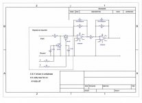
This is what I used. R1 selected to suit the input in question such that all input sources subjectively have the same level. The section with R1 is repeated to cover as many inputs as needed.

The honest answer is that all the amps I've owned (commercial ones) and also ones I've built that have used standard diff input stages all have a 'saminess' about the sound quality and none have come close to this one for delivering a really enjoyable musical presentation.Why don't you like differential pairs so much?
That's the only reason
Long time absent...i see very good progress here but i have a question for you rephil.
Why you need a buffer?
Is it necessary or just your choice?
Regards
thimios
Hi Thimios
It is not necessary to put a buffer when using a CD reader, its output is low Ohm having a few volts high output, and the amp works just fine with a (needed attenuation) rotary switch of 10kOhm alone. You get in the attached the JPG of the buffer I did put for Mooly's power amp.
As I will as always do some try with other kind of stuff (at the moment, unknown stuff) that can produce signals we can hear when connected to a power amp, I will add an input buffer.
Thus I did a try using a buffer using a TL072CP, I did hear a degaradation to the sound produced when connected to the CD reader that before was not present without the buffer. So I did do some try with other op amps I had home. The result is that they are some small hearable differences to me in the sound produced by a very simple buffer that is in use. I am very unhappy with this situation as my hears have now only limited capacity in the high frequencies (at around 75 years it is likely to be a bit down, I am an old man). So above 10KHz I am not interested as I can't hear that.
Thus, a simple buffer (gain at 1, being a non inverting buffer, with limited input frequency below 250kHz) that makes hearable changes in the sound to me is very painful to my brain : how is this possible ? I am very unconfortable with people that say they hear differences that small like sub 0.001% distortion in the sound produced by a power amp, and now I say the same kind of things as they do say, do I really hear that ?
So today I did a try that nobody would say usefull : I did try a LM358. Yes I did that, and it is a very good sound that is produced, but not at all like the goodness of sound produced by a LM4562 or even like a TL072CP ! I might maybe try a LT1013 later. I want to know that too. And what to say with an LT1115 ? But the latter cannot a substitute to the LM4562 in my PCB.
Gremlins I am pretty sure there is not anyone, trolls there are some, I even know some of them. So my results here are only facts for me without any rational explanation. Sorry.
Have a very nice day my friend
Best regards
rephil
Attachments
- Home
- Amplifiers
- Solid State
- My MOSFET amplifier designed for music

