
So this is the buffer. X1 gain, DC coupled and non inverting. One practical point is that bjt opamps like the 5532 will show a significant DC offset due to the 200k input bias resistor.
The input filter rolls the response off as shown here.
View attachment 1072527
Yes Mooly, it is exactly what I did. As you know, the corner frequency is Fc = 1 /(2x PI x R xC) where R is 2000 Ohm and C = 330pF. So Fc = 241 kHz. I did write above Fc is below 250kHz. Your plot shows the same thing. I did choose that frequency because the power amp has a cut off frequency (I did measure it for both channels) of 170kHz.
In the power amp, a significant DC offset generated before the input is blocked by the C1 = 10uF that you did put at the input. So even 1 volt of DC offset will not be a problem for your very nice and good sounding power amp. So do I believe. If somehow I am wrong, please say it, I will be very happy to learn something new for me.
As you see, I have taken no interest at the phase generated at higher frequencies. As said, I don't hear frequencies above 10kHz. The stereo impression I have in my lab is so good that I have no doubt it will be more than OK when I will have my Mooly's amp driving my Canton's speakers. Let me say that better so in bad english : I expect to get "a more better" stereo effect with them later in a better sounding room with better placed speakers.
As your amp has nothing digital inside, nothing could reenter at lower frequencies generated using a sample frequency not twice as high as the highest frequency inside the amp (the Nyquist frequency rules). Aliasing is a nasty thing when performing some FFT of a signal ...
I am happy with your power amp Mooly. It sounds great here.
Be happy too Mooly, having a good end of this day.
Best regards
rephil
In the power amp, a significant DC offset generated before the input is blocked by the C1 = 10uF that you did put at the input. So even 1 volt of DC offset will not be a problem for your very nice and good sounding power amp. So do I believe. If somehow I am wrong, please say it, I will be very happy to learn something new for me.
Absolutely correct
 but (there's always one
 ") ) if you feed the opamp output into a pot and there is DC present then the pot might be a bit noisy as you turn it, more so as they wear and get older.
) if you feed the opamp output into a pot and there is DC present then the pot might be a bit noisy as you turn it, more so as they wear and get older.Be happy too Mooly, having a good end of this day.
and you.Hi Mooly
I'm new to English and often don't understand what it means. You answered easphyx's question, "Why don’t you like differential pairs?" 'Saminess' I don't understand the meaning of. Can you tell me more about it?
And while you probably use OP-AMPs a lot at the line level, most voltage-feedback op amps use differential pairs. Do you feel that 'saminess' in those sounds as well?
Saminess... having the same underlying subjective sound quality to it.
and one that is not easy to answer. When it comes to opamps I genuinely believe that there are subtle audible differences between various types when spec sheets suggest that should not be so. So it is difficult to compare an opamp with discrete because all our digital sources and the whole recording chain are packed full of opamps.
So I'm going to flip what you ask on its head and suggest that the single ended power amp topology simply has audible qualities (distortion profile, transient behaviour and so on) that I actually prefer. The design brief was that it should be 'designed for music' and it has that 'wow', that sounds good ability about it.
So back to opamps... if they were all replaced by discrete single ended versions and circuitry adapted to suit then it might well be 'to much of a good thing' audibly and the final result not as good.
Good questionAnd while you probably use OP-AMPs a lot at the line level, most voltage-feedback op amps use differential pairs. Do you feel that 'saminess' in those sounds as well?
and one that is not easy to answer. When it comes to opamps I genuinely believe that there are subtle audible differences between various types when spec sheets suggest that should not be so. So it is difficult to compare an opamp with discrete because all our digital sources and the whole recording chain are packed full of opamps.So I'm going to flip what you ask on its head and suggest that the single ended power amp topology simply has audible qualities (distortion profile, transient behaviour and so on) that I actually prefer. The design brief was that it should be 'designed for music' and it has that 'wow', that sounds good ability about it.
So back to opamps... if they were all replaced by discrete single ended versions and circuitry adapted to suit then it might well be 'to much of a good thing' audibly and the final result not as good.
It means a trait. Something they seem to have in common,
Take cars as an example. All three cylinder petrol engines have a saminess about them. They might be really good in many ways but you can always pick one out from a group of four cylinder engines. And the same applies to the four cylinder. They all have their own characteristic. Its up to the driver to decide which they prefer and why.
Take cars as an example. All three cylinder petrol engines have a saminess about them. They might be really good in many ways but you can always pick one out from a group of four cylinder engines. And the same applies to the four cylinder. They all have their own characteristic. Its up to the driver to decide which they prefer and why.
Thank you for the detailed explanation. I finally got the meaning of 'saminess'.
By the way, I would like to point out a point that seems to be a purely circuit problem.
I noticed by looking at the "relay delay is required for 6 seconds" simulation waveform of # 1215, but if the actual circuit is equivalent to this simulation circuit, there seems to be a large peak around 6 to 7 Hz outside the audible band.
The DC servo is returned to the non-inverting input side using an inverting integrator. However, this method is affected by the time constant of the input low-cut filter and the passive servo on the inverting input side, in addition to the time constant of the integrator circuit. Since it becomes the low frequency characteristic of the secondary system or the tertiary system, a large peak occurs depending on the arrangement of the poles, and in the worst case, low frequency oscillation occurs.
It also has the disadvantage that this characteristic is affected by the signal source resistance of the connected equipment.
For example, it would be good if the circuit placed in front of it taht was fixed, such as the Integrated Amplifier
I recommend that you check it out.
By the way, I would like to point out a point that seems to be a purely circuit problem.
I noticed by looking at the "relay delay is required for 6 seconds" simulation waveform of # 1215, but if the actual circuit is equivalent to this simulation circuit, there seems to be a large peak around 6 to 7 Hz outside the audible band.
This can lead to unwanted woofer cone vibrations. Mooly may not be using but, for example it can be a problem when playing vinyl records.
The DC servo is returned to the non-inverting input side using an inverting integrator. However, this method is affected by the time constant of the input low-cut filter and the passive servo on the inverting input side, in addition to the time constant of the integrator circuit. Since it becomes the low frequency characteristic of the secondary system or the tertiary system, a large peak occurs depending on the arrangement of the poles, and in the worst case, low frequency oscillation occurs.
It also has the disadvantage that this characteristic is affected by the signal source resistance of the connected equipment.
For example, it would be good if the circuit placed in front of it taht was fixed, such as the Integrated Amplifier
I recommend that you check it out.
You make what could be a valid point for vinyl users if they perhaps use a front end that has extended LF response without any rumble filters.
If I were to revisit and update the design then I'm sure there would be things I would do differently. This was all designed around 18 years ago, long before I used a PC at home
The amp does what it says on the tin It is designed for music reproduction and in that it excels.
If I were to revisit and update the design then I'm sure there would be things I would do differently. This was all designed around 18 years ago, long before I used a PC at home
The amp does what it says on the tin
It is designed for music reproduction and in that it excels.Hi Mooly
I have mostly finished to put all what is needed for getting this nice sounding amplifier in a good chassis. I have still to drill holes for connecting the feet I have and after that closing the chassis all is done.
Well, I have still some problems too.
I have been driven mad with the problem related to a ground loop. As there are no output ground for the speakers on the PCBs, I have driven both the output to the protection PCB using a wire from the ground on the PSU. (The protection PCB introduces a delay at power on and verifiy that there is no big dc (more than around 1 V dc at the output)). I have also the ground from the PSU connected to each power amp pcb. This introduces a ground loop in some way that I don't understand. Having disconnected the ground from one power amp pcb : all is again OK without ground loop ... I don't understand how this is possible, but it works fine.
I have also a problem with the bandwith of the power amps. When not in the chassis, I did measure it at around 170kHz. Now in the chassis, the same amps provide a bandwith of around 90kHz. Well, it is nice and enough, but Mooly you did say that your amp had a bandwith of 120kHz. So I have a problem : where come the RC from that attenuates the bandwith ? When out of the chassis, I did not use the RC174 that I use now for the input wires, and at the time for these input wires I used very short normal electrical wires I had around, without any problem.
As you understand, the amp is always very good sounding as before : thank you Mooly ! But I like to understand what occurs, and it is a real pain for me not understanding what happens.
As for the heatsinks I did use for the small transistors, they work fine, but mechanically when placing all the stuff in the chassis, they let see that it is very easy to damage the transistors when placing some unwanted force on the heatsink ...
When satisfied of the job, I will post some pictures of what I did here, and after that I will connect the power amp to my principal speakers from Canton.
Best regards
rephil
Last edited:
Have a look at this old post and thread:
https://www.diyaudio.com/community/threads/3-stage-lin-topology-nfb-tappings.101321/post-1624677
Have a look through that thread as it touches on these issues.
Run your speaker returns back to the main star point taken as a spur from the main PSU reservoir caps.
The bandwidth issue is strange. You need to confirm the input voltage to the power amp input remains constant as you sweep through the frequency range. The only thing I could imagine altering the HF bandwidth would be interaction of the load with the output inductor. That is easy to prove, just measure the output directly at the NFB takeoff point which is the junction of the two 0.22 ohm resistors.
Saminess... having the same underlying subjective sound quality to it.
Thank you for answering.
But I still couldn't understand the meaning of 'saminess'.
@Mooly
How is it with your native language proficiency?
;)Please check below for the difference between Saminess VS sameness:
https://en.wiktionary.org/wiki/Saminess
VS.
https://www.dictionary.com/browse/sameness
sameness
noun
- the state or quality of being the same; identity; uniformity.
- lack of variety; monotony.
PS. We have Sami minority people here in Northern Finland.
Hi rephil,pictures please...
I want to see the RCA position and connections.
Hi Thimios
You have got mail with heavy pictures.
Thank you my friend.
Best regards
rephil
Please check below for the difference between Saminess VS sameness:
Just my spelling of it. I wasn't even sure it was a real word tbh although I am familiar with the Sami people.
Hi Mooly
I have had some problem in order to get the reason why I did measure a bandwith of around 90kHz, coming from 170kHz when all the circuits were not placed inside the chassis.
It is a strange reason I did find for this attenuation of the bandwidth. I have used all RG174 for the connection at low level, from the RCAs to the PCBs amplifiers. This RG174 wire was very old, more than 40 years home. The gnd part of the wire did not solder in less than more than 20seconds, and it look bad soldered ... As it is to much heat, I did check that there was electrical continuity, there was. Then I did clamp the RG174 with a metallic part in order to solder new RG174 at the gnd part of the wires, so I did get a better bandwith of around 145kHz. Already better, but not what I had before. Look at the 'old built with RG174 and other stuff not needed.jpg'. The last part has been to substitute the RG174 with another wire I did buy at the same time (around 40 years ago) as the RG174, but all Cu inside, and the gnd part did solder easily as you would expect it. I have provided a Bode Plot.pdf of what I have now : it shows an healthy 172kHz. All OK for me.
I have modded the internal of the amplifier taking away what is not needed for the power amp using CD reader. You get a picture of what I had built before with the RG174 and all other stuff not needed. With the very friendly help of the good Thimios, I have arranged a bit the internal of the road of the wires that substitute the RG174.
It follows in the next part.
Best regards
rephil
Attachments
-
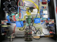 old built with RG174 and other stuff not needed.JPG521.1 KB · Views: 115
 -
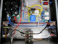 New wires, away what not needed.JPG546.5 KB · Views: 126
 -
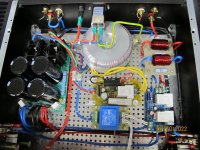 New wires away what not needed second.JPG500.2 KB · Views: 120
 -
 No input, from nasty old built.JPG326.7 KB · Views: 106
 -
 New no input both channel .JPG354.2 KB · Views: 110
Hi Mooly
Here is the second part.
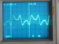
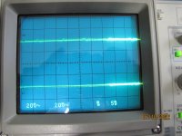
As you see, the no input from the nasty built did provide bad sound : it is possible to hear it with the music. The new buit does not provide anything out of my speakers at all levels. Without input they are silent.
Here, please find the Bode Plot of the new built, the input probe is placed at the input of the amplifier PCB, the output probe is placed at the output of the amplifier built. The gain is obviosly not the one that is written as between the input of the generator placed at the input of the power amp built, so it gets attenuated at the PCB input. I did put a bit more volume as <hat I normally use for the CD when connected. The blue track is the gain, the brown track is the phase.
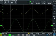
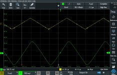
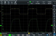
Some other pictures, one that shows with more details the no input situation at the output, the others are sine, triangular and rectangular at 1kHz and 50kHz : Yellow track is measured at the input of the PCB, green track is the output at the outside of the power amp.
I have problem to download pictures in diyaudio : they don't accept .docx and .bmp files. So I did have to let the files translated in .pdf and .jpg using free available programs on the webb. They are around free as when you have many pictures to translate, they ask you to pay ...
If you thing it is a good built : don't believe that, as I would do it a lot different today with what I did learn. As did Thimios say : I would group the RCAs together at a better place as they are placed now. But what I have got is a very good working amp without disturbing sound (buzz and others), and as I have so much pain in my bones, in particular in my hands, I have to consider it veery well done and finished ...
Don't hesitate to give your opinions in order to get a better done power amp : it is not my last power amp, and other good guys here are doing their best in order to get good music where they are living.
Dear Mooly, this amp sounds great, and in the next days I will test it on my principal speakers, and if all is OK (if it sounds at least as good as in my lab), it will be my only principal power amp ! Thank you Mooly, it is the best amp I have heard.
Best regards
rephil
Here is the second part.
As you see, the no input from the nasty built did provide bad sound : it is possible to hear it with the music. The new buit does not provide anything out of my speakers at all levels. Without input they are silent.
Here, please find the Bode Plot of the new built, the input probe is placed at the input of the amplifier PCB, the output probe is placed at the output of the amplifier built. The gain is obviosly not the one that is written as between the input of the generator placed at the input of the power amp built, so it gets attenuated at the PCB input. I did put a bit more volume as <hat I normally use for the CD when connected. The blue track is the gain, the brown track is the phase.
Some other pictures, one that shows with more details the no input situation at the output, the others are sine, triangular and rectangular at 1kHz and 50kHz : Yellow track is measured at the input of the PCB, green track is the output at the outside of the power amp.
I have problem to download pictures in diyaudio : they don't accept .docx and .bmp files. So I did have to let the files translated in .pdf and .jpg using free available programs on the webb. They are around free as when you have many pictures to translate, they ask you to pay ...
If you thing it is a good built : don't believe that, as I would do it a lot different today with what I did learn. As did Thimios say : I would group the RCAs together at a better place as they are placed now. But what I have got is a very good working amp without disturbing sound (buzz and others), and as I have so much pain in my bones, in particular in my hands, I have to consider it veery well done and finished ...
Don't hesitate to give your opinions in order to get a better done power amp : it is not my last power amp, and other good guys here are doing their best in order to get good music where they are living.
Dear Mooly, this amp sounds great, and in the next days I will test it on my principal speakers, and if all is OK (if it sounds at least as good as in my lab), it will be my only principal power amp ! Thank you Mooly, it is the best amp I have heard.
Best regards
rephil
Attachments
-
Sine at 1kHz.pdf1.7 MB · Views: 58
-
 Sine at 50kHz.jpg150 KB · Views: 65
 -
Triangular-at-1kHz.pdf1.7 MB · Views: 60
-
 Triangular at 50kHz.jpg149.7 KB · Views: 68
 -
rectangular-at-1kHz.pdf1.7 MB · Views: 65
-
 Rectangular at 50kHz.jpg146.7 KB · Views: 67
 -
Noise-measuring-at-the-PCB-input.pdf1.7 MB · Views: 91
-
Bode-Plot.pdf2.7 MB · Views: 76
Thank you Mooly, it is the best amp I have heard.
Thats nice to hear
I'm pleased you are pleased.It all looks a very neat build you have done
RG174 I know as 50 ohm coax aerial cable so maybe not the best option What I see in the pictures looks much more suitable. Your test results all look good.I have problem to download pictures in diyaudio : they don't accept .docx and .bmp files
They will attach if you put them in a zipped folder provided it is within the attachment file size limits.
Hi Mooly,Thats nice to hear
It all looks a very neat build you have done
They will attach if you put them in a zipped folder provided it is within the attachment file size limits.
A zipped folder to attach the files not accepted by diyaudio : thank you Mooly ! It is a solution.
Yesterday I did close the chassis and I did bring the amp downstairs and attached it to my main speakers (big Canton's that can reproduce 18Hz at -3dB, there is nothing low like that in the music as far as I know). So now I can say and believe that you did produce this wonderful amplifier only for my Canton's speakers. They sing like never until now ! Bass are extremely good, better as the Honey Badger that for the time (it will change) is located below your amplifier ... Now I have a much better sound as what I did get in my lab ... When there is a silence in the music, I look if all is OK, as no sound at all is terrific ! Bass are extraordinary good, powerful and low when there are in the music to be reproduced. The high frequencies are perfect. The voice is perfect, well, I am more than happy and this amp did now become my main and best amplifier connected to my main speakers.
Thank you Mooly, your amp make my day ! I am so happy to get so good music !
best regards
rephil
That's strangeA zipped folder to attach the files not accepted by diyaudio
If you go to the bottom of the page and click on 'Terms and rules' there is a button for attachments. Zip is in there.Thank you Mooly, your amp make my day ! I am so happy to get so good music !
Well I am really pleased and happy you are enjoying it
- Home
- Amplifiers
- Solid State
- My MOSFET amplifier designed for music