Output inductors aren't really detrimental in any way and they do provide an additional layer of safety. If the layout and construction of the amp is good then it almost certainly would be fine without the inductor as long as the 0.22 ohm series output R of the original was preserved.
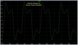
Out of curiosity, I ran some square 0.5V 20kHz wave simulations in an 8Ω with a 1μ capacitive load. The response of the series only resistor vs inductor is interesting. Both do address the issue. This does seem to further suggest that the inductor isn't necessary as long as the series resistor is used - though the responses are different. I also looked at the response if the series resistor is lowered from 0.22Ω to 0.1Ω - This does not sufficiently dampen the ringing.
Attachments
Indeed so ")
In the 'Inductor Network and Series Output Resistor' the distorted shape you see is purely at the output end of the coil, the amplifier output itself will be an undistorted version. Adding the coil juts makes it bulletproof no matter what you dangle on the end.
You can play around with resistors and coils in simulation without the amp.

Try this. Use the .par line on the sim to change rise time, frequency and amplitude:

In the 'Inductor Network and Series Output Resistor' the distorted shape you see is purely at the output end of the coil, the amplifier output itself will be an undistorted version. Adding the coil juts makes it bulletproof no matter what you dangle on the end.
You can play around with resistors and coils in simulation without the amp.
Try this. Use the .par line on the sim to change rise time, frequency and amplitude:
Attachments
The only affect I see from the inductor is a bit of rounding in the square wave response, which also affects slew rate. It's negligible at 1K and increases with frequency. At 20k, slew rate appears to drop from 10 to 6. Though as you stated, it does add a bit more safety.

One other observation - depending on the design an series output resistor may not dampen capacitive ringing at all capacitive loads. Your design does seem to do this, but in other designs I tinkered with, it worked well for larger capacitive loading, but did not fair will with lighter loading.
So as you stated, better to add the coil if you want to be on the safer side.
So as you stated, better to add the coil if you want to be on the safer side.
Thank you, Mr. Mooly, and all the contributors. We are gathered here for the same hobbies. First of all, English is not my native language (using translation software), and this is also my first time posting here
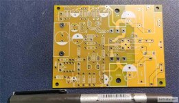
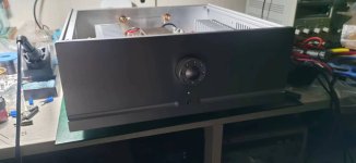
After studying the published PCB, I made this amplifier last month and also conducted some testing on it. The indicators were very good, and it was posted for future reference.
Overall layout

output DC 0.1mv

SNR AC0.3mv

rmaa test


After studying the published PCB, I made this amplifier last month and also conducted some testing on it. The indicators were very good, and it was posted for future reference.
Overall layout
output DC 0.1mv
SNR AC0.3mv
rmaa test
Attachments
Thank you for the compliment, Mr. mooly, I still have a puzzle, the amplifier takes a bit long to establish the working point, there will be a "buzzing" sound when it is turned on, it is an AC sound, it takes 1 minute to disappear, and I have not modified the parameters of the electronic componentsThanks for posting and I'm really pleased you are enjoying the amp. You have done a good job there.
to brian92fs
The AC on my side is 220v, 50hz
Last edited:
The operating point should fully settle after around 8 seconds and this is confirmed by the DC offset settling at 0.00 volts. It takes that long because of the time constant of the servo used for biasing and is the reason I stress the need for a reliable speaker relay delay on the speaker outputs. It should not take any longer.
If you switch on with no speakers connected and then wait a few seconds and then connect the speaker you should not hear any noises. If you do then something is amiss in the construction somewhere.
If you switch on with no speakers connected and then wait a few seconds and then connect the speaker you should not hear any noises. If you do then something is amiss in the construction somewhere.
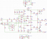
Pin 4 of the TLO71 is the negative supply rail, pin 6 is an output voltage and would be in the -5 to -6 region on a correctly working amp.
R5 is the current setting resistor in the constant current source and will always have around 0.6 volts across the resistor. I'm not really understanding what you are asking

R5 is the current setting resistor in the constant current source and will always have around 0.6 volts across the resistor. I'm not really understanding what you are asking
Forgive my English level, in #1434 I described the problem of long work point establishment, although I solved it with electronic filtering + CRC, but this problem is still there, I wonder if it is the cause of low voltage? For example, the R5 (100R) is only 580mv, and the opa pin6 output is only -5.02v?

Also: After adding electronic filtering, the auditory timbre has changed, but I personally like it
Also: After adding electronic filtering, the auditory timbre has changed, but I personally like it
Attachments
The long time it takes to settle (the working point) is because of the time constant of the DC servo. You can not really avoid that. These parts are the 0.1uF cap and 1 meg resistor connected to the - input of the opamp.
That's good
Also: After adding electronic filtering, the auditory timbre has changed, but I personally like it
That's good - Home
- Amplifiers
- Solid State
- My MOSFET amplifier designed for music