And finally I worked out where the 5.5K dip is coming from. It corresponds exactly to the width of the baffle to the start of the chamfer. so I guess that is a good reason for chamfering the baffle, it pushes up the frequency that the baffle diffraction happens at.
Wow, could you please illustrate on a photo where the baffle may be affecting the dip?
And finally I worked out where the 5.5K dip is coming from. It corresponds exactly to the width of the baffle to the start of the chamfer. so I guess that is a good reason for chamfering the baffle, it pushes up the frequency that the baffle diffraction happens at.
Hmm, are you are confusing baffle step response with edge diffraction.
It sounds like edge diffraction is the source of the problem. Rounding the corners requires the edge radius to be equal to the wavelength (or larger) of the offending wave. That could be several inches (2.6" to be exact) in radius to be effective.
You could try relocating the tweeter so that it is not centered on the baffle. The only other recourse is increasing the radius of the edge or what I did was fold back the baffle at about 30° to lesson the diffraction effect.
An externally hosted image should be here but it was not working when we last tested it.
Hi Get-Lit and Loren. Yes it is edge diffration I was talking about, though I'm going to have to check the measurement again because looking back at it it doesn't sound right.
I think I measured from the centre to the beginning of the chamfer but 62mm seems to be too small as the width from edge to edge (of the chamfer) *should* be about 150mm which would correspond to a freq of surprise surprise my ugly dip point around 2200 Hz....
In my haste to find a reason for the dip at 5.5K (which shows on both the tweeter and the midbass measurements) I found out the wavelength at 5.5K and ran a tape measure over the front of the baffle, and my recollection was that the two matched (but now I'm uncertain).
I'm pretty sure I have measured these woofers not on the baffle and seen the same dip around 2K but I'm now wondering whether I have an unfortunate natural dip at this freq which is re-inforced by my chosen baffle geometry! (which the quick and dirty measurement in post 58 would tend to support...)
Post 6 in this thread has the BDS simulation of how the baffle diffraction should affect the freq response. It is looking scarily accurate for the unchamfered baffle, but Not showing the predicted benefits of the chamfered baffle in post #7.
I'm actually not that concerned about the 5.5K small dip, it is the big one at around 2k that bugs me. But I'm going to get some 6.4mm felt to put on the baffles and see how that affects things. Redesigning the box at this point isn't an option")
The chamfer is about 25mm I will do some more measurements again this weekend of both chamfered and non-chamfered baffles now that I have a slightly better measurement setup (the quick and dirty measurements in post 58 definitely showed a difference, but it could have been due to speaker positioning maybe).
I know a lot of people say that small chamfers have no effect, I'm not entirely convinced, the main reason I have only chamfered one at this stage is so I can get conclusive evidence one way or the other
Tony.
I think I measured from the centre to the beginning of the chamfer but 62mm seems to be too small as the width from edge to edge (of the chamfer) *should* be about 150mm which would correspond to a freq of surprise surprise my ugly dip point around 2200 Hz....
In my haste to find a reason for the dip at 5.5K (which shows on both the tweeter and the midbass measurements) I found out the wavelength at 5.5K and ran a tape measure over the front of the baffle, and my recollection was that the two matched (but now I'm uncertain).
I'm pretty sure I have measured these woofers not on the baffle and seen the same dip around 2K but I'm now wondering whether I have an unfortunate natural dip at this freq which is re-inforced by my chosen baffle geometry! (which the quick and dirty measurement in post 58 would tend to support...)
Post 6 in this thread has the BDS simulation of how the baffle diffraction should affect the freq response. It is looking scarily accurate for the unchamfered baffle, but Not showing the predicted benefits of the chamfered baffle in post #7.
I'm actually not that concerned about the 5.5K small dip, it is the big one at around 2k that bugs me. But I'm going to get some 6.4mm felt to put on the baffles and see how that affects things. Redesigning the box at this point isn't an option
The chamfer is about 25mm I will do some more measurements again this weekend of both chamfered and non-chamfered baffles now that I have a slightly better measurement setup (the quick and dirty measurements in post 58 definitely showed a difference, but it could have been due to speaker positioning maybe).
I know a lot of people say that small chamfers have no effect, I'm not entirely convinced, the main reason I have only chamfered one at this stage is so I can get conclusive evidence one way or the other
Tony.
Hi Get-Lit and Loren. Yes it is edge diffration I was talking about talking about, though I'm going to have to check the measurement again because looking back at it it doesn't sound right.
I think I measured from the centre to the beginning of the chamfer but 62mm seems to be too small as the width from edge to edge (of the chamfer) *should* be about 150mm which would correspond to a freq of surprise surprise my ugly dip point around 2200 Hz....
In my haste to find a reason for the dip at 5.5K (which shows on both the tweeter and the midbass measurements) I found out the wavelength at 5.5K and ran a tape measure over the front of the baffle, and my recollection was that the two matched (but now I'm uncertain).
I'm pretty sure I have measured these woofers not on the baffle and seen the same dip around 2K but I'm now wondering whether I have an unfortunate natural dip at this freq which is re-inforced by my chosen baffle geometry! (which the quick and dirty measurement in post 58 would tend to support...)
Post 6 in this thread has the BDS simulation of how the baffle diffraction should affect the freq response. It is looking scarily accurate for the unchamfered baffle, but Not showing the predicted benefits of the chamfered baffle in post #7.
I'm actually not that concerned about the 5.5K small dip, it is the big one at around 2k that bugs me. But I'm going to get some 6.4mm felt to put on the baffles and see how that affects things. Redesigning the box at this point isn't an option
The chamfer is about 25mm I will do some more measurements again this weekend of both chamfered and non-chamfered baffles now that I have a slightly better measurement setup (the quick and dirty measurements in post 58 definitely showed a difference, but it could have been due to speaker positioning maybe).
I know a lot of people say that small chamfers have no effect, I'm not entirely convinced, the main reason I have only chamfered one at this stage is so I can get conclusive evidence one way or the other
Tony.
1" radius is not likely enough to make a real dent in the problem. You need to be more than 2" and probably closer to 3".
OK My memory from getting out the tape measure to the time I posted was obviously a bit on the flaky side The measurement of 62mm is actually the distance from the centre of the tweeter to the roll surround on the midbas... so I have propagated some completely false information!!! Sorry everyone!
I'll do some measurements tomorrow after putting the legs on the second box so that I can make sure that the only difference between the boxes is the chamfer. Will also be very careful positioning the boxes to make sure all things are equal.
Tony.
The measurement of 62mm is actually the distance from the centre of the tweeter to the roll surround on the midbas... so I have propagated some completely false information!!! Sorry everyone! I'll do some measurements tomorrow after putting the legs on the second box so that I can make sure that the only difference between the boxes is the chamfer. Will also be very careful positioning the boxes to make sure all things are equal.
Tony.
Hi Get-Lit and Loren. Yes it is edge diffration I was talking about talking about, though I'm going to have to check the measurement again because looking back at it it doesn't sound right.
I think I measured from the centre to the beginning of the chamfer but 62mm seems to be too small as the width from edge to edge (of the chamfer) *should* be about 150mm which would correspond to a freq of surprise surprise my ugly dip point around 2200 Hz....
In my haste to find a reason for the dip at 5.5K (which shows on both the tweeter and the midbass measurements) I found out the wavelength at 5.5K and ran a tape measure over the front of the baffle, and my recollection was that the two matched (but now I'm uncertain).
I'm pretty sure I have measured these woofers not on the baffle and seen the same dip around 2K but I'm now wondering whether I have an unfortunate natural dip at this freq which is re-inforced by my chosen baffle geometry! (which the quick and dirty measurement in post 58 would tend to support...)
Post 6 in this thread has the BDS simulation of how the baffle diffraction should affect the freq response. It is looking scarily accurate for the unchamfered baffle, but Not showing the predicted benefits of the chamfered baffle in post #7.
I'm actually not that concerned about the 5.5K small dip, it is the big one at around 2k that bugs me. But I'm going to get some 6.4mm felt to put on the baffles and see how that affects things. Redesigning the box at this point isn't an option
The chamfer is about 25mm I will do some more measurements again this weekend of both chamfered and non-chamfered baffles now that I have a slightly better measurement setup (the quick and dirty measurements in post 58 definitely showed a difference, but it could have been due to speaker positioning maybe).
I know a lot of people say that small chamfers have no effect, I'm not entirely convinced, the main reason I have only chamfered one at this stage is so I can get conclusive evidence one way or the other
Tony.
1" radius is not likely enough to make a real dent in the problem. You need to be more than 2" and probably closer to 3".
I looked over your drawings in your first posts and saw a baffle width of about 200 mm.
The baffle step loss F3 for that width would be about 575 Hz.
Also, try clamping on some wings or flat extensions onto either side of the cabinet and see if the frequency response changes. You should easily be able to predict baffle step loss and diffraction effects and compare theory with observed data.
It is very easy to get to chasing your tail when testing speakers. You need to approach the problem with a paranoid attitude and question every measurement (is this really valid). I recommend testing the same thing multiple ways to see if the tests agree.
It is easy to get errors because there is so many things to think about. Also, the room where you are doing the measurements can make life hell. Gating only does so much.
Thanks Loren I've done measurements in all sorts of places but they always seem to have the same massive dip at around 2Khz, this just doesn't seem to change regardless of how I mount the speaker in what room, or position of mic etc. I can try adding some width to see how it affects the measurements. Also I can try going out on the balcony, have just been lazy as dragging the computer out there is no small task Probably the other thing I should do is re-read my "testing loudspeakers" by Joe D'appolito... I remember thinking ahhh to a few things when I read it the first time, but it was a while ago, and I have forgotten.
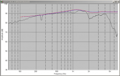
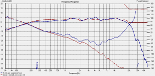
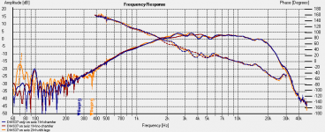
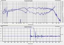
I've attached a comparison of what BDS (baffle diffraction simulator) says the response will be like compared to actual, the baffle step prediction from the sim follows pretty closely all things considered, so I don't think there is anything strange going on there. It is what happens after 1.6K that bugs me, certainly isn't something the sim thinks should happen with my baffle geometry.
Black is the actual measured response at 1M. Ignore the big drop at 200Hz that was a problem with me turning on calibration in holm impulse and it screwing up the phase.
Blue is the sim with chamfer, and red is the sim without chamfer (minimal difference, but for the tweeter the chamfer seems to make a bit more of a difference).
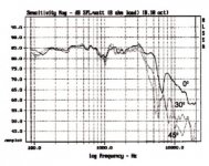
I've also attached a somewhat interesting plot from the morel isreal sites mw144 datasheet. Note the original datasheet I saw for the MW144 was very different to this, but it has some interesting similarities to what I have measured. Strange that the dip seems to be at 1K for them but 2K for me but other than that looks rather similar to me...
Tony.
I've done measurements in all sorts of places but they always seem to have the same massive dip at around 2Khz, this just doesn't seem to change regardless of how I mount the speaker in what room, or position of mic etc. I can try adding some width to see how it affects the measurements. Also I can try going out on the balcony, have just been lazy as dragging the computer out there is no small task Probably the other thing I should do is re-read my "testing loudspeakers" by Joe D'appolito... I remember thinking ahhh to a few things when I read it the first time, but it was a while ago, and I have forgotten. I've attached a comparison of what BDS (baffle diffraction simulator) says the response will be like compared to actual, the baffle step prediction from the sim follows pretty closely all things considered, so I don't think there is anything strange going on there. It is what happens after 1.6K that bugs me, certainly isn't something the sim thinks should happen with my baffle geometry.
Black is the actual measured response at 1M. Ignore the big drop at 200Hz that was a problem with me turning on calibration in holm impulse and it screwing up the phase.
Blue is the sim with chamfer, and red is the sim without chamfer (minimal difference, but for the tweeter the chamfer seems to make a bit more of a difference).
I've also attached a somewhat interesting plot from the morel isreal sites mw144 datasheet. Note the original datasheet I saw for the MW144 was very different to this, but it has some interesting similarities to what I have measured. Strange that the dip seems to be at 1K for them but 2K for me but other than that looks rather similar to me...
Tony.
Attachments
Last edited:
Thanks Loren
I've attached a comparison of what BDS (baffle diffraction simulator) says the response will be like compared to actual, the baffle step prediction from the sim follows pretty closely all things considered, so I don't think there is anything strange going on there. It is what happens after 1.6K that bugs me, certainly isn't something the sim thinks should happen with my baffle geometry.
Black is the actual measured response at 1M. Ignore the big drop at 200Hz that was a problem with me turning on calibration in holm impulse and it screwing up the phase.
Blue is the sim with chamfer, and red is the sim without chamfer (minimal difference, but for the tweeter the chamfer seems to make a bit more of a difference).
I've also attached a somewhat interesting plot from the morel isreal sites mw144 datasheet. Note the original datasheet I saw for the MW144 was very different to this, but it has some interesting similarities to what I have measured. Strange that the dip seems to be at 1K for them but 2K for me but other than that looks rather similar to me...
Tony.
Where is your crossover point?
Also, have you taken on-axis and off-axis plots of the drivers individually without crossovers?
The two woofers should be connected together, but having those plots will tell you is there is a driver or phase issue.
What about far field response of about 2 meters?
Last, have you tried near field response?
The two woofers should be connected together, but having those plots will tell you is there is a driver or phase issue.
What about far field response of about 2 meters?
Last, have you tried near field response?
Hi Loren,
post #60 has off access and nearfiled measurements (though the off axis were all drivers running with 4.3uF on the tweeter, and guestimates for the angle). crossover point is very high, around 5 - 6 K 1st order woofers are running full range. I've tried simming the crossover in speaker workshop using the measurements taken for the woofers and tweeter, but can't get anything like the actual measured response with the cap, so I suspect something is wrong somewhere.
Measurements with single MW144 or both running are virtually identical (levels excluded).
You've given me plenty to think about, and a more methodical approach is necessary, rather than me taking random measurements
Cheers,
Tony.
Zaph has a little note the 2k dip on the test of a SEAS Nextel driver.
"Response is smooth and extended except for a wideband dip centered on 1kHz. This is not as bad as it seems, because in a normal width box, there is usually a diffraction peak there. on top of the 6dB 2pi to 4pi space conversion, there is often another couple dB of diffraction ripple starting with a peak at 1kHz and a dip at 2.3kHz or so."
I haven't read the full thread but you can check out if this dip moves or disappears if you extend the width to say 600mm by adding a temporary extension to the baffle width in a symmetric or asymmetric arrangement.
Hi Rabbitz Thanks that does appear to be what is happening (in both the BDS sim and in real life).
I did some more measurements on Saturday, most telling of which was a 0.5M measurement of an MW144 without any baffle at all. I just screwed it to the base of my measuring platform. The 2Khz dip remained!! I think it must be a basket reflection. I did the measurement at 0.5M because of the reduced height above the floor, but in hind sight I should also have measured one woofer in box at that distance as well for a direct comparison. Certainly the box seems to help rather than hinder in smoothing out the irregularities.
I also took new measurements at 1M and 2M distance, both measurements are almost identical with only very small deviations at a couple of points most likely some extra reflections on the 2M response that the gating couldn't deal with.
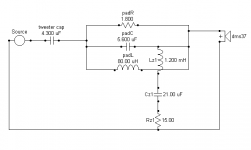
I put the measured tweeter and midbass response curves and also the measured impedance curves into Jeff Bagby's Passive Crossover Designer spreadsheet (Excellent highly recomended) and told it I had a 4.3uF cap only on the tweeter and the simulated response was quite a close match to my measured response at 2M with the cap in place. So I think I finally have some measurements that are useful
I decided since I had a sim that appeared to be quite accurate, I might as well accept the fact that there wasn't anything mechanical I could do to smooth out the response (which when I look at it, isn't THAT bad really) and instead try tackling it electrically. The result of that excercise looks promising and I'm off to Jaycar when they open to buy some cheap bipolar electros and a few coils and resistors for prototyping the crossover I came up with, just to see whether it is even in the ball park. If it looks (and more importantly sounds) good then I will order some more Axon caps and probably some Jantzen audio coils and mills resistors. Somehow though I think the chances of it turning out like my sim are a little on the low side, which is why I'm not going to divulge more till I've tried it, otherwise someone might talk me out of it, as it is not particularly conventional..... I guess that is to be expected with me... If it fails I'll only have spent about $30 on parts so will be a relatively cheap lesson.
Anyway below are some of the measurements taken on Sat and the Simulated response from the crossover I have designed. Obviously if it works as simmed, AND sounds good, I'll be extremely happy!
Oh and there definitely is a difference between the chamfered and non chamferd box, and it isn't necessarily a positive one! but I'll save that for another post
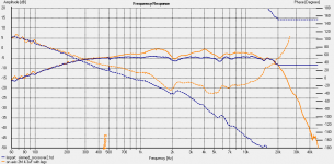
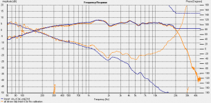
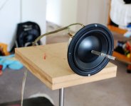
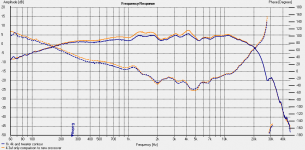
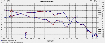
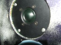
1sat pic is 2M measurements of mw144's and DMs37. 2nd image is 0.5cm measurement of MW144 no box (as per nearfield picture at right). Third is the orange actual measured freq response at 1M with just 4.3uF cap, and blue the simmed response derived from separate 2M measurements of MW144 and DMS37 and simmed with 4.3uF cap... pretty good correlation if you ask me!!! 4th Image is again the orange actual measured response with 4.3u cap, and Blue Simmed with my proposed crossover.
Tony.
I did some more measurements on Saturday, most telling of which was a 0.5M measurement of an MW144 without any baffle at all. I just screwed it to the base of my measuring platform. The 2Khz dip remained!! I think it must be a basket reflection. I did the measurement at 0.5M because of the reduced height above the floor, but in hind sight I should also have measured one woofer in box at that distance as well for a direct comparison. Certainly the box seems to help rather than hinder in smoothing out the irregularities.
I also took new measurements at 1M and 2M distance, both measurements are almost identical with only very small deviations at a couple of points most likely some extra reflections on the 2M response that the gating couldn't deal with.
I put the measured tweeter and midbass response curves and also the measured impedance curves into Jeff Bagby's Passive Crossover Designer spreadsheet (Excellent highly recomended) and told it I had a 4.3uF cap only on the tweeter and the simulated response was quite a close match to my measured response at 2M with the cap in place. So I think I finally have some measurements that are useful
I decided since I had a sim that appeared to be quite accurate, I might as well accept the fact that there wasn't anything mechanical I could do to smooth out the response (which when I look at it, isn't THAT bad really) and instead try tackling it electrically. The result of that excercise looks promising and I'm off to Jaycar when they open to buy some cheap bipolar electros and a few coils and resistors for prototyping the crossover I came up with, just to see whether it is even in the ball park. If it looks (and more importantly sounds) good then I will order some more Axon caps and probably some Jantzen audio coils and mills resistors. Somehow though I think the chances of it turning out like my sim are a little on the low side, which is why I'm not going to divulge more till I've tried it, otherwise someone might talk me out of it, as it is not particularly conventional..... I guess that is to be expected with me...
If it fails I'll only have spent about $30 on parts so will be a relatively cheap lesson. Anyway below are some of the measurements taken on Sat and the Simulated response from the crossover I have designed. Obviously if it works as simmed, AND sounds good, I'll be extremely happy!
Oh and there definitely is a difference between the chamfered and non chamferd box, and it isn't necessarily a positive one! but I'll save that for another post
1sat pic is 2M measurements of mw144's and DMs37. 2nd image is 0.5cm measurement of MW144 no box (as per nearfield picture at right). Third is the orange actual measured freq response at 1M with just 4.3uF cap, and blue the simmed response derived from separate 2M measurements of MW144 and DMS37 and simmed with 4.3uF cap... pretty good correlation if you ask me!!! 4th Image is again the orange actual measured response with 4.3u cap, and Blue Simmed with my proposed crossover.
Tony.
Attachments
Last edited:
OK well I guess it won't come as a surprise to anyone that the result of putting the sim into practice wasn't quite the same Whilst it didn't work to the degree it did in the sim, it certainly made an improvement both in measurements and in a listening test
The coils from jaycar (measured with speaker workshop) were pretty much spot on.. the 0.05mH one measure 0.049 and the 0.1 mH one measured 0.098 I didn't measure the other two before soldering them to a board (something I should have waited to do until I'd done the measurements.
The bipolar electros on the other hand are not quite as effective as they should be. The 22uF in the 4k notch filter cut it by one db, when I replaced it with a couple of paralleled 11uF axon polyprops the cut became 2db, but still a long way off the sims 4db. Oh and in order to get that 2db I had to increase the resistor from 4.7 ohms to 8.2 ohms. some more experimenting with values between 4.7 and 8 is in order as going above 8 results in the peak going up. I also suspect that a slight increase in the coils value might also help. Perhaps I will need to do some coil winding after all. I was hopeful I could avoid it, but it is not looking like it.
The fact that the bipolar isn't pulling its weight in the 4K notch makes me think that the one in the 1K notch might also be part of the reason it didn't match the sim. This notch filter also seems to be very sensitive (in the sim) to resistor values so I'm thinking of adding .2 or .3 ohms and see what effect it has.
Anyway Despite the fact that it didn't quite turn out like the sim I think it has been a good result. The speakers definitely sound better, and I have learned that bipolar electros don't appear to be a good choice for notch filters (even for prototyping!) I would still like to cut back that 4K peak a little more I suspect it is causing a little bit of edginess.
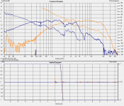
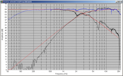
Anyway here is a graph showing the new crossover measurement (blue trace) compared to the old orange trace (just a 4.3uF cap on the tweeter). and also the measured versus the simmed response.
So slowly I'm getting there
Tony.
Whilst it didn't work to the degree it did in the sim, it certainly made an improvement both in measurements and in a listening test The coils from jaycar (measured with speaker workshop) were pretty much spot on.. the 0.05mH one measure 0.049 and the 0.1 mH one measured 0.098 I didn't measure the other two before soldering them to a board (something I should have waited to do until I'd done the measurements.
The bipolar electros on the other hand are not quite as effective as they should be. The 22uF in the 4k notch filter cut it by one db, when I replaced it with a couple of paralleled 11uF axon polyprops the cut became 2db, but still a long way off the sims 4db. Oh and in order to get that 2db I had to increase the resistor from 4.7 ohms to 8.2 ohms. some more experimenting with values between 4.7 and 8 is in order as going above 8 results in the peak going up. I also suspect that a slight increase in the coils value might also help. Perhaps I will need to do some coil winding after all. I was hopeful I could avoid it, but it is not looking like it.
The fact that the bipolar isn't pulling its weight in the 4K notch makes me think that the one in the 1K notch might also be part of the reason it didn't match the sim. This notch filter also seems to be very sensitive (in the sim) to resistor values so I'm thinking of adding .2 or .3 ohms and see what effect it has.
Anyway Despite the fact that it didn't quite turn out like the sim I think it has been a good result. The speakers definitely sound better, and I have learned that bipolar electros don't appear to be a good choice for notch filters (even for prototyping!) I would still like to cut back that 4K peak a little more I suspect it is causing a little bit of edginess.
Anyway here is a graph showing the new crossover measurement (blue trace) compared to the old orange trace (just a 4.3uF cap on the tweeter). and also the measured versus the simmed response.
So slowly I'm getting there
Tony.
Attachments
Current state of play.
Well on the weekend I decided I better get my act together and chamfered the second box. I also purchased some satin polyurathane in a spray can and put a coat on the baffle. Doesn't look too bad (until you look closely) I've sanded it back and giving it another coat, not sure how many I will do yet, but I think the second coat should be better.
I also decided to dremel out the back of the speaker cutout some more, hopefully will give the drivers a bit more breathing space. I've only done it on the one that was getting the other treatment so still haven't listened to the result. I'm going to have to sand down and re burnish again too. The surface has gone VERY rough. Interestingly it appears to be a reaction to the air, as the one without legs, when I lifted it up, the bottom was still as smooth as the day I finished it. Hopefully the grain won't lift any more after a second application.
I also decided to try the crossover simulator in speaker workshop again, since the results I got after using the passive crossover designer spreadsheet were far from reality. Using the same measurements I used in the PCD spreadsheet, the result for the simmed crossover and the actual result were in fairly close agreement. Still not exact, but MUCH better. after experimenting a bit I worked out the problem. The PCD spreadsheet, whilst it allows you to enter the DCR of coils in the "crossover" bit, it doesn't allow you to enter it in the "extra circuitry" bits. SO the inductors in the notch filters were being calculated as perfect inductors without any DCR at all, when I put in no DCR in speakerworkshop I got similar results to the PCD spreadsheet!
So what I have decided is that PCD is good for quickly tuning a notch filter to the desired freq, but then take the results and sim the same thing in speakerworkshop to get a more realistic estimate of how it will perform in the real world.
It didn't help that the original 4K notch I had come up with was actually a 5K notch but the PCD sim was showing the effects off centre (which in reality didn't exist at all) There is already a huge drop at 5K with these drivers so It didn't appear to make any difference at all. So I redid the sims and found that I could get something functional (but not optimal) with the 100 uH coils I had (instead of the 50uH ones I'd originally bought) so I could do another measurement and compare the simmed to the actual results.
Well the 4K peak is gone, and there is a much better correlation between the sim and the measurement so I am making progress I think
The sound was quite different, at first listen (only one speaker) I wasn't sure I liked it, but after a while I realised it did actually sound more natural. It's funny though, I now think the tweeter sounds too hot... Oddly the speakers sound best at about 80 degrees off axis
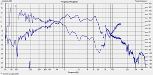
Anyway below is a plot showing the simulation of the crossover from the individual measurements, and the actual measurement at two meters.
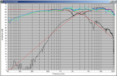
There is a lot in this first chart.
The aqua trace is the actual measured result of the original attempt at a 1K and 4K notch filter on the MW144's.
The Blue trace is the simulated "new" suboptimal crossover after combining the Mw144 and DMS37 graphs.
The green trace is the actual measured implementation of this simmed crossover.
The black traces are the individual drivers as modified by the crossover.
The red traces are Target responses which are 2nd order Bessel.
I've also attached the "planned" crossover sim Blue trace is the simmed response with the addition of nearfield data spliced it at 365Hz before running through the sim.
Now I'm not expecting to get this exact result, but if it comes in as close as the other sim did then I think that it will be a pretty good result!
Note that there is NO BSC in this design, There isn't even a first order filter on the MW144's.
The whole thing may be rather unconventional, but seems to do the trick.
Hopefully changing from the 100uF electro to a polyprop will make the filter perform a little closer to the sim. Also hoping that some of the edginess might go with the zobel on the tweeter and by using some decent resistors instead of the "white coffins" that I've got at present.
I'm going to have a go at winding my own coils, as I need lower dcr than the ones I've got from Jaycar to have a hope of matching the simmed performance, and it will also give me some room to move with adjusting the values if I wind them a little larger than planned and then slowly unwind till I get the right value.
Tony.
Well on the weekend I decided I better get my act together and chamfered the second box. I also purchased some satin polyurathane in a spray can and put a coat on the baffle. Doesn't look too bad (until you look closely) I've sanded it back and giving it another coat, not sure how many I will do yet, but I think the second coat should be better.
I also decided to dremel out the back of the speaker cutout some more, hopefully will give the drivers a bit more breathing space. I've only done it on the one that was getting the other treatment so still haven't listened to the result. I'm going to have to sand down and re burnish again too. The surface has gone VERY rough. Interestingly it appears to be a reaction to the air, as the one without legs, when I lifted it up, the bottom was still as smooth as the day I finished it. Hopefully the grain won't lift any more after a second application.
I also decided to try the crossover simulator in speaker workshop again, since the results I got after using the passive crossover designer spreadsheet were far from reality. Using the same measurements I used in the PCD spreadsheet, the result for the simmed crossover and the actual result were in fairly close agreement. Still not exact, but MUCH better. after experimenting a bit I worked out the problem. The PCD spreadsheet, whilst it allows you to enter the DCR of coils in the "crossover" bit, it doesn't allow you to enter it in the "extra circuitry" bits. SO the inductors in the notch filters were being calculated as perfect inductors without any DCR at all, when I put in no DCR in speakerworkshop I got similar results to the PCD spreadsheet!
So what I have decided is that PCD is good for quickly tuning a notch filter to the desired freq, but then take the results and sim the same thing in speakerworkshop to get a more realistic estimate of how it will perform in the real world.
It didn't help that the original 4K notch I had come up with was actually a 5K notch but the PCD sim was showing the effects off centre (which in reality didn't exist at all) There is already a huge drop at 5K with these drivers so It didn't appear to make any difference at all. So I redid the sims and found that I could get something functional (but not optimal) with the 100 uH coils I had (instead of the 50uH ones I'd originally bought) so I could do another measurement and compare the simmed to the actual results.
Well the 4K peak is gone, and there is a much better correlation between the sim and the measurement so I am making progress I think
The sound was quite different, at first listen (only one speaker) I wasn't sure I liked it, but after a while I realised it did actually sound more natural. It's funny though, I now think the tweeter sounds too hot... Oddly the speakers sound best at about 80 degrees off axis
Anyway below is a plot showing the simulation of the crossover from the individual measurements, and the actual measurement at two meters.
There is a lot in this first chart.
The aqua trace is the actual measured result of the original attempt at a 1K and 4K notch filter on the MW144's.
The Blue trace is the simulated "new" suboptimal crossover after combining the Mw144 and DMS37 graphs.
The green trace is the actual measured implementation of this simmed crossover.
The black traces are the individual drivers as modified by the crossover.
The red traces are Target responses which are 2nd order Bessel.
I've also attached the "planned" crossover sim Blue trace is the simmed response with the addition of nearfield data spliced it at 365Hz before running through the sim.
Now I'm not expecting to get this exact result, but if it comes in as close as the other sim did then I think that it will be a pretty good result!
Note that there is NO BSC in this design, There isn't even a first order filter on the MW144's.
The whole thing may be rather unconventional, but seems to do the trick.
Hopefully changing from the 100uF electro to a polyprop will make the filter perform a little closer to the sim. Also hoping that some of the edginess might go with the zobel on the tweeter and by using some decent resistors instead of the "white coffins" that I've got at present.
I'm going to have a go at winding my own coils, as I need lower dcr than the ones I've got from Jaycar to have a hope of matching the simmed performance, and it will also give me some room to move with adjusting the values if I wind them a little larger than planned and then slowly unwind till I get the right value.
Tony.
Attachments
Last edited:
The results of chamfered vs non-chamfered
Well I thought I'd revisit this statement I made earlier:
I'd like to think it was the extensive playing with the BDS sim trying different things that resulted in this but ....
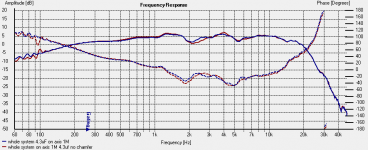
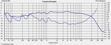
Anyway the graphs are below: In all cases the blue trace is the response of the speaker with the 22mm chamfer all round. The red is the unchamfered box. The orange trace on the 1st graph is the trace with the legs on the box. After getting a shock as to how much more lumpy the tweeter response was with the chamfer I decided to see what it would be like with the legs on. I think that when the box was sitting on the measurement platform without the legs, the V formed between the speaker and the platform was having a negative impact. I'll have to also try a measurement with some foam in there completely blocking the gap between the speaker and the stand.
I was very careful to make sure all measurements were taken with the speaker in the exact same position, I used the same drivers (in the same positions in the boxes) for each test and did the tests again and compared to the first ones (they were identical) just to rule out any differences due to swapping the boxes. The measurements were at 1M distance on axis with the tweeter 1.4M off the floor.
Whilst I think this proves (to my satisfaction) that a chamfer of only 22mm does make a difference, that difference is not particularly significant, and depending on the circumstances, may not even be desirable!!
My original statement that it had an effect on the response at 5.5Khz whilst not completely incorrect (the dip is slightly bigger) was completely wrong in all other respects as the frequency response of the tweeter was much more heavily affected with the addition of ripple with a magnitude of around +- 2.5db between 2000 and 7000 Hz!!!
Note that the total system response was taken with only a 4.3uF on the tweeter and no other crossover components.
One thing I will say though. For my taste, with the chamfer the boxes are a LOT more aesthetically pleasing
Tony.
Well I thought I'd revisit this statement I made earlier:
The graph of the tweeter response is the most telling, and looking at it you would probably come to the immediate conclusion that the chamfer was detrimental, but funnily enough, when you look at the summed response it is actually a little smoother. Whether this is luck or good management I'm not sureOh and there definitely is a difference between the chamfered and non chamferd box, and it isn't necessarily a positive one! but I'll save that for another post
I'd like to think it was the extensive playing with the BDS sim trying different things that resulted in this but ....Anyway the graphs are below: In all cases the blue trace is the response of the speaker with the 22mm chamfer all round. The red is the unchamfered box. The orange trace on the 1st graph is the trace with the legs on the box. After getting a shock as to how much more lumpy the tweeter response was with the chamfer I decided to see what it would be like with the legs on. I think that when the box was sitting on the measurement platform without the legs, the V formed between the speaker and the platform was having a negative impact. I'll have to also try a measurement with some foam in there completely blocking the gap between the speaker and the stand.
I was very careful to make sure all measurements were taken with the speaker in the exact same position, I used the same drivers (in the same positions in the boxes) for each test and did the tests again and compared to the first ones (they were identical) just to rule out any differences due to swapping the boxes. The measurements were at 1M distance on axis with the tweeter 1.4M off the floor.
Whilst I think this proves (to my satisfaction) that a chamfer of only 22mm does make a difference, that difference is not particularly significant, and depending on the circumstances, may not even be desirable!!
My original statement that it had an effect on the response at 5.5Khz whilst not completely incorrect (the dip is slightly bigger) was completely wrong in all other respects as the frequency response of the tweeter was much more heavily affected with the addition of ripple with a magnitude of around +- 2.5db between 2000 and 7000 Hz!!!
Note that the total system response was taken with only a 4.3uF on the tweeter and no other crossover components.
One thing I will say though. For my taste, with the chamfer the boxes are a LOT more aesthetically pleasing
Tony.
Attachments
Last edited:
Hi Tony,
Sorry the post above was refering to the tweet graph specificely.(more likely, diffraction issue).
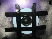
Try something like this next time your testing, just to see what happens to your worm line. The material I've used here is just that camping foam, (kind of a pathetic attempt at a mattress) you can buy down the 2 dollar shop. For obvious reasons, (in my case), I can hear the difference easily between having it taped on there or not.
Maybe try something similar around your entire baffle? for science sake ya know
Dunno how to calculate it, but the ripple there wouldn't be a reflection off the mic back onto the baffle back on to the mic or something similar? Just another dumb idea.
Mick.
Sorry the post above was refering to the tweet graph specificely.(more likely, diffraction issue).
Try something like this next time your testing, just to see what happens to your worm line. The material I've used here is just that camping foam, (kind of a pathetic attempt at a mattress) you can buy down the 2 dollar shop. For obvious reasons, (in my case), I can hear the difference easily between having it taped on there or not.
Maybe try something similar around your entire baffle? for science sake ya know
Dunno how to calculate it, but the ripple there wouldn't be a reflection off the mic back onto the baffle back on to the mic or something similar? Just another dumb idea.
Mick.
Attachments
Last edited:
Ahh I thought you were talking about the 2K dip I just did a sim with the tweeter inverted and it has a MUCH bigger dip like 30dB big!
I did actually put some felt on the baffle around the tweeter also stuck on with black insulation tape but it looks like I didn't keep the measurement. first one was with a small hole, and it severly dropped the sensitivity of the tweeter, I guess not surprising since it is a semi horn. the second one with bigger hole did make a difference, but I can't remember what it was... will have to revisit
I can definitely understand why your foam is making a difference. On my original test box I had the woofers mounted flush with the baffle, and I recessed the tweeter deeper as well (with a slightly rounded over lip) to keep the time alignment (these drivers are time aligned if the tweeter is flush mounted and the woofers surface mounted). It caused some very big irregularities in the high freq response! I'd have the measurements somewhere but finding them would be difficult, and they were done before I had my setup sorted out too, but the difference (in the measurements) was very apparent when I put some foam in the recess to bring the tweeter back to flush with the baffle!
The thing I find most interesting is that it is purely the chamfer that is making the difference, without it, the response is smooth as. I recon it is the bottom chamfer that is the problem, I'll have to do some more tests trying to remove it by filling it with some foam. It's funny, I ummed and arred about whether to put that bottom chamfer on, It may not have been the wisest choice. however as can be seen the overall response is not that affected, with the ripple convieniently up where the mw144s are down, and down where they are up
What is really scary is the measurement I did with the speaker in it's normal spot and (admitedly a different mic, but still a WM60AY) at my listening position! My room absolutely sucks!!
have a look gated to just before the first REALLY big reflection, If I show the response with that in it, it is laughable!! What I found really interesting was the fact that the peaks were all on even multiples ie 2k 4k 6k 8k 10k, and the dips were 3k 5k 7k 9k.. weird.. No doubt some standing waves happening!
actually I just 1/3rd octave smoothed that (second graph) and it doesn't look so bad
Tony.
like 30dB big! I did actually put some felt on the baffle around the tweeter also stuck on with black insulation tape
but it looks like I didn't keep the measurement. first one was with a small hole, and it severly dropped the sensitivity of the tweeter, I guess not surprising since it is a semi horn. the second one with bigger hole did make a difference, but I can't remember what it was... will have to revisit I can definitely understand why your foam is making a difference. On my original test box I had the woofers mounted flush with the baffle, and I recessed the tweeter deeper as well (with a slightly rounded over lip) to keep the time alignment (these drivers are time aligned if the tweeter is flush mounted and the woofers surface mounted). It caused some very big irregularities in the high freq response! I'd have the measurements somewhere but finding them would be difficult, and they were done before I had my setup sorted out too, but the difference (in the measurements) was very apparent when I put some foam in the recess to bring the tweeter back to flush with the baffle!
The thing I find most interesting is that it is purely the chamfer that is making the difference, without it, the response is smooth as. I recon it is the bottom chamfer that is the problem, I'll have to do some more tests trying to remove it by filling it with some foam. It's funny, I ummed and arred about whether to put that bottom chamfer on, It may not have been the wisest choice. however as can be seen the overall response is not that affected, with the ripple convieniently up where the mw144s are down, and down where they are up
What is really scary is the measurement I did with the speaker in it's normal spot and (admitedly a different mic, but still a WM60AY) at my listening position! My room absolutely sucks!!
have a look
gated to just before the first REALLY big reflection, If I show the response with that in it, it is laughable!! What I found really interesting was the fact that the peaks were all on even multiples ie 2k 4k 6k 8k 10k, and the dips were 3k 5k 7k 9k.. weird.. No doubt some standing waves happening! actually I just 1/3rd octave smoothed that (second graph) and it doesn't look so bad
Tony.
Attachments
- Status
- This old topic is closed. If you want to reopen this topic, contact a moderator using the "Report Post" button.
- Home
- Loudspeakers
- Multi-Way
- My Morel MTM Project