Thanks Josh and thunk ") probably will be next weekend before the next serious work occurs, though I might see if I can trim the veneer tonight, as leaving it untrimmed is asking for trouble with a 21 month old running around , I unfortunately don't have anywhere "safe" I can put it...
probably will be next weekend before the next serious work occurs, though I might see if I can trim the veneer tonight, as leaving it untrimmed is asking for trouble with a 21 month old running around , I unfortunately don't have anywhere "safe" I can put it...
Tony.
probably will be next weekend before the next serious work occurs, though I might see if I can trim the veneer tonight, as leaving it untrimmed is asking for trouble with a 21 month old running around , I unfortunately don't have anywhere "safe" I can put it...Tony.
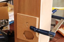
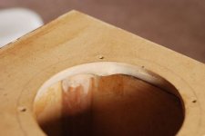
Well I took Tuesday Off, was owed some time in lieue, so today I trimmed the veneer on the back pannel and drilled the binding post holes (they were allready drilled through the mdf, just needed to do the veneer. The reason they were pre-drilled in the mdf was that the inside needed to be routed to accomodate the nuts.
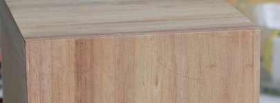
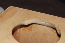
Anyway it didn't go completely without drama. I learned today that I should pre-trim the veneer to maybe a mm or so within the cabinet edge (with a stanley knife or similar) before setting the router loose on it. The long sides had a tendency to have the veneer split off rather than get cut by the router bit. Luckily only a small split happened at the bottom of the box, and a bit of super glue has fixed that up reasonably well. since this is the back I'm not too concerned. You can see the glued in bit of veneer in the top left of the closeup photo.
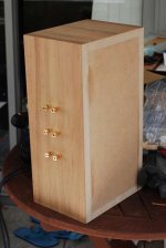
I couldn't resist putting the binding posts in just to have a look, of course the veneer hasn't been finished yet but I think it looks ok I've allowed for maximum flexibility. One set of binding posts for each driver. 6 channel gainclone anyone seriously though I will initially have an external crossover, but it does leave me the option of bi or even tri amping at a later date (there will already be a biamping happening with the bass units but that is another story.
Anyway usual set of pics. The other box is currently out on the balcony with its bottom piece of veneer gluing down. I think I did a bit better job with the filling on this one, but it still isn't perfect...
1st pic I placed a piece of scrap MDF (this one was used for testing the routing of my tweeter cutouts, and also the routing of the inside of the back baffle for the binding post nuts) to drill through into. was mostly successful, still got a tiny bit of splitting of the veneer around the hole.
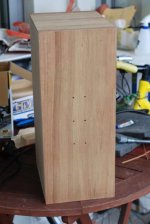
2nd pic holes drilled and veneer trimmed. 3rd pic closeup showing the repair. 4th pic binding posts attached
Tony.
Anyway it didn't go completely without drama. I learned today that I should pre-trim the veneer to maybe a mm or so within the cabinet edge (with a stanley knife or similar) before setting the router loose on it. The long sides had a tendency to have the veneer split off rather than get cut by the router bit. Luckily only a small split happened at the bottom of the box, and a bit of super glue has fixed that up reasonably well. since this is the back I'm not too concerned. You can see the glued in bit of veneer in the top left of the closeup photo.
I couldn't resist putting the binding posts in just to have a look, of course the veneer hasn't been finished yet but I think it looks ok
I've allowed for maximum flexibility. One set of binding posts for each driver. 6 channel gainclone anyone seriously though I will initially have an external crossover, but it does leave me the option of bi or even tri amping at a later date (there will already be a biamping happening with the bass units but that is another story. Anyway usual set of pics. The other box is currently out on the balcony with its bottom piece of veneer gluing down. I think I did a bit better job with the filling on this one, but it still isn't perfect...
1st pic I placed a piece of scrap MDF (this one was used for testing the routing of my tweeter cutouts, and also the routing of the inside of the back baffle for the binding post nuts) to drill through into. was mostly successful, still got a tiny bit of splitting of the veneer around the hole.
2nd pic holes drilled and veneer trimmed. 3rd pic closeup showing the repair. 4th pic binding posts attached
Tony.
Attachments
Tony, That looks way to tight. It looks as if the clearance on the bottom of the woofer is near to zero. Is it?
Terry
Little did I know when I replied to this post that you were probably one of (if not) the most authoritative person on DIY-Audio to be making that call (when it comes to these drivers) Even more ironic was the next comment I made. I did find the email and my memory didn't fail me, a small amount of silicon applied with a syringe was the recommendation
... I've not done anything yet about this but most certainly will. Could you give me the diameter of the cutout you normally use for the MW144's so I know how far to take them out I'm hesitant to use the silicon, as I don't really want to "glue" the drivers in. Will certainly be doing some experimenting with damping material and as I have fixed baffles, the only way to change will be taking the drivers in and out.
cheers,
Tony.
Little did I know when I replied to this post that you were probably one of (if not) the most authoritative person on DIY-Audio to be making that call (when it comes to these drivers) Even more ironic was the next comment I made. I did find the email and my memory didn't fail me, a small amount of silicon applied with a syringe was the recommendation
I'm hesitant to use the silicon, as I don't really want to "glue" the drivers in. Will certainly be doing some experimenting with damping material and as I have fixed baffles, the only way to change will be taking the drivers in and out.
cheers,
Tony.
Hi Tony, 118mm is what I use. To fix your problem I would :
Mark out where the screws will go and mark those locations so they are left as is. Now heavily chamfer the rest of the back out. Use a heavy file or you could try a jigsaw, its arkward.
Other options for sealing are to use a soft rubber section 5mm x 5mm. You can get this at rubber stores. A 6mm round also works well.
Hope this helps.
Terry
Little did I know when I replied to this post that you were probably one of (if not) the most authoritative person on DIY-Audio to be making that call (when it comes to these drivers) Even more ironic was the next comment I made. I did find the email and my memory didn't fail me, a small amount of silicon applied with a syringe was the recommendation
I'm hesitant to use the silicon, as I don't really want to "glue" the drivers in. Will certainly be doing some experimenting with damping material and as I have fixed baffles, the only way to change will be taking the drivers in and out.
cheers,
Tony.
One other way is this, works VERY well.
Take a largish following router bit. These are the ones with the roller on the bottom. Change the roller to a smaller one. Run the roller so it just functions. You will cut the difference between the rollar sizes. Change to a router bit with the roller on top or use your routers following attachement. Its lots of work changing bits but it works.
Terry
Yes it does! Thanks Terry I just checked and my cutouts are 118mm so I feel a bit better now! I think part of the problem may be the photo's I took were through from the back and I couldn't get a good angle. I can definitely take them out more with the dremel (which is what I resorted to originally after finding a wood rasp a bit tough going). I wasn't sure how much was too much!
I've just taken a few additional pictures, It is really hard to try and show the chamfer with the camera! It always looks much flatter than it really is. To give an idea, the distance from the cutout to the inside edge is 18mm and the baffle is 25mm thick so the chamfer is going the full thickness of 25 mm over a distance of 18mm.. it is not a straight angle though and is convex, I did that in an attempt to make reflections less likely, though on such a small radius that is probably not going to have any effect... perhaps I should have gone concave instead...
Tony.
I just checked and my cutouts are 118mm so I feel a bit better now! I think part of the problem may be the photo's I took were through from the back and I couldn't get a good angle. I can definitely take them out more with the dremel (which is what I resorted to originally after finding a wood rasp a bit tough going). I wasn't sure how much was too much! I've just taken a few additional pictures, It is really hard to try and show the chamfer with the camera! It always looks much flatter than it really is. To give an idea, the distance from the cutout to the inside edge is 18mm and the baffle is 25mm thick so the chamfer is going the full thickness of 25 mm over a distance of 18mm.. it is not a straight angle though and is convex, I did that in an attempt to make reflections less likely, though on such a small radius that is probably not going to have any effect... perhaps I should have gone concave instead...
Tony.
Attachments
Yes it does! Thanks Terry
I've just taken a few additional pictures, It is really hard to try and show the chamfer with the camera! It always looks much flatter than it really is. To give an idea, the distance from the cutout to the inside edge is 18mm and the baffle is 25mm thick so the chamfer is going the full thickness of 25 mm over a distance of 18mm.. it is not a straight angle though and is convex, I did that in an attempt to make reflections less likely, though on such a small radius that is probably not going to have any effect... perhaps I should have gone concave instead...
Tony.
It may also be that you mounted the drivers when the box was other than flat on its back. You have more clearance on the top as opposed to the bottom. See if you can reposition the driver so that it is even. I suggest you have taken out enough. Looks good. Just for the future, I often make my baffles out of two layers. The outside layer is 16mm HD3, (from Laminex industries) This is the layer I fix the drivers to. The next layer is whatever you want, just to add more 'meat'. The driver holes in the second layer are larger by as much as you want. I like having my cake and eating it too.
Terry
Last edited:
Thanks again Terry I'll check for centering next time I mount the drivers! Thanks for the tip about the front baffles. I've been considering doing some sort of laminate for when I finally get around to doing the woofer enclosures (though I was only thinking along the lines of some 16mm MDF laminated with some 9mm marine ply.... I assume the HD3 is more expensive than normal MDF, hence only using for the baffles and not the whole enclosures?
Tony.
I'll check for centering next time I mount the drivers! Thanks for the tip about the front baffles. I've been considering doing some sort of laminate for when I finally get around to doing the woofer enclosures (though I was only thinking along the lines of some 16mm MDF laminated with some 9mm marine ply.... I assume the HD3 is more expensive than normal MDF, hence only using for the baffles and not the whole enclosures? Tony.
Thanks again Terry
Tony.
Hi Tony, it is 3 times the density, equivalent to 48mm. It is also 3 times the price! Certainly doable for small boxes. They will be good boxes. I suggest you glue 6-12 mm of good ply to the hd3. 16mm of anything is thin, too thin for good corners.
Terry
Thanks Terry and Bob
I can see the next project is going to be a bit of a leap from the first I decided since the MTM's were my first ever venture into making my own cabinets that I should try and keep it simple. Since I'm relatively happy with how they have gone, turning it up a notch for the next seems reasonable. BUT I do have to get these finished first I'll hopefully have a much better work area in a few months (if not sooner) so things should start rolling then
If I do desire, I can always make some new cabinets for the MTM's at some point in the future if I felt it was going to give me any advantage, however at this point I'll wait and see...
Tony.
I can see the next project is going to be a bit of a leap from the first
I decided since the MTM's were my first ever venture into making my own cabinets that I should try and keep it simple. Since I'm relatively happy with how they have gone, turning it up a notch for the next seems reasonable. BUT I do have to get these finished first I'll hopefully have a much better work area in a few months (if not sooner) so things should start rolling then If I do desire, I can always make some new cabinets for the MTM's at some point in the future if I felt it was going to give me any advantage, however at this point I'll wait and see...
Tony.
Thanks Terry and Bob
I can see the next project is going to be a bit of a leap from the first
If I do desire, I can always make some new cabinets for the MTM's at some point in the future if I felt it was going to give me any advantage, however at this point I'll wait and see...
Tony.
Once they are finished, sit back, enjoy the music, now say, "I did that."
Well done.
Terry
I Intend to! I could put the drivers in them right now, but I know if I do I won't want to take them out again... I've only listened to the combo in mono (single box for prototype), and did so for hours. I'm showing a lot of restraint by not bolting the drivers in and setting them up. I'm determined that these ones will be finished properly!
It won't be anything like your level of finish Terry, but it will be a far cry from raw chipboard like my old faithfuls (which have only recently received a coat of paint after more than 20 years
Tony.
I could put the drivers in them right now, but I know if I do I won't want to take them out again... I've only listened to the combo in mono (single box for prototype), and did so for hours. I'm showing a lot of restraint by not bolting the drivers in and setting them up. I'm determined that these ones will be finished properly! It won't be anything like your level of finish Terry, but it will be a far cry from raw chipboard like my old faithfuls (which have only recently received a coat of paint after more than 20 years
Tony.
Well I haven't posted for a while, but I have been slowly chipping away. I felt today was a significant step in the progress though. One box now has 5 sides veneered (I'm not doing the baffle) so that means appart from trimming of the veneer on the two sides done this weekend, the application of the veneer is complete for one box.
I was hoping to get both done this weekend, but I'm not sure about the weather conditions this afternoon, very very windy outside at the moment not to mention about 40 degrees C so the second box might have to wait till next weekend.
Unfortunately I had some chunking problems when trimming the top of the boxes Might need to invest in a better quality veneer trimming bit (probably a tungsten carbide one... I think the one I have has dulled after very little use, and I'm not really great at sharpening it. . The problem occurs when trimming the end grain (I guess it could also be speed related, but it is ironic that the first time I had a problem was on the surface that actually matters..... I guess it could also be due to not having used enough glue at the edges... The chunks that came out are small but will be noticable on close inspection... I might have to get some wood coloured filler or maybe mix up some wood dust and pva and fill it with that to hopefully make it a little less obvious.
After that the chamfering of the front baffle is the next major job, though I would really like to do some measurements before I do that so I have some before and after measurements to show to what degree (if any) the chamfers affect the freq response.
Then I need to worry about finishing!!! I'd been thinking about spraying the baffle a satin black, but I guess I could also finish it with whatever I finish the veneer with... I'm not sure that would be a good idea though, especially if I use oil!! Masking of the veneer to do the spraying of the baffle is going to be tricky... I Chose to do the veneering before the chamfering because I felt I'd get a better result but it does make things tricky from a finishing perspective... Oh well I guess I'll deal with it when I get to it
Anyway a picture of the momentous occasion of gluing on the last bit of veneer!
Tony.
I was hoping to get both done this weekend, but I'm not sure about the weather conditions this afternoon, very very windy outside at the moment not to mention about 40 degrees C so the second box might have to wait till next weekend.
Unfortunately I had some chunking problems when trimming the top of the boxes
Might need to invest in a better quality veneer trimming bit (probably a tungsten carbide one... I think the one I have has dulled after very little use, and I'm not really great at sharpening it. . The problem occurs when trimming the end grain (I guess it could also be speed related, but it is ironic that the first time I had a problem was on the surface that actually matters..... I guess it could also be due to not having used enough glue at the edges... The chunks that came out are small but will be noticable on close inspection... I might have to get some wood coloured filler or maybe mix up some wood dust and pva and fill it with that to hopefully make it a little less obvious. After that the chamfering of the front baffle is the next major job, though I would really like to do some measurements before I do that so I have some before and after measurements to show to what degree (if any) the chamfers affect the freq response.
Then I need to worry about finishing!!! I'd been thinking about spraying the baffle a satin black, but I guess I could also finish it with whatever I finish the veneer with... I'm not sure that would be a good idea though, especially if I use oil!! Masking of the veneer to do the spraying of the baffle is going to be tricky... I Chose to do the veneering before the chamfering because I felt I'd get a better result but it does make things tricky from a finishing perspective... Oh well I guess I'll deal with it when I get to it
Anyway a picture of the momentous occasion of gluing on the last bit of veneer!
Tony.
Attachments
OK one veneered and trimmed box. It's not perfect. a few chips here and there, but I guess since this is my first attempt at veneering anything I shouldn't be too surprised. I did something really dumb today, let the router bit hit the end grain before it was properly up to speed, ripped chunks out.. not big but enough to be visible... one consolation was it was at the bottom rather than the top. Also showed me that the speed was important so I cranked it to maximum and found it did a much cleaner job on the end grain (was a new bit, no burning at high speed like the old one).
Also learned that I should start in the middle and work out to the end when going with the grain (still making sure to go in the opposite direction to the bit's rotation). luckily that split off was at the front which is going to be chamfered.... It does make me wonder whether I have glued properly or not. Certainly no problems with bubbles or unevenness though.
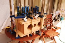
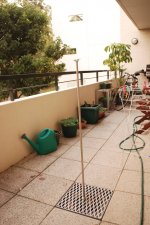
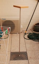
I also had a flash of inspiration yesterday. We had a floor lamp which was starting to show signs of becoming dangerous.. strange popping noises (and intermittently working... It was sitting out on the balcony waiting for a chance to dismantle to a size that could be disposed of. Then I noticed that it unscrewed, and that the actual shaft was pretty strong stainless steel. It had a big bolt on the bottom and a bracket on the top. I've been thinking I have to make a speaker testing stand for some time, and I Had been thinking that the balcony was the place to do it, but I hadn't worked out how I would make something sturdy enough to hold the speaker at a reasonable height... Then I decided to see whether I could attach the bolt to the drain grill on the balcony floor.. voila!!!! All I need to do is screw my veneer caul (for the tops of the boxes) to the bracket and I have my stand I wouldn't be game to use it on a windy day (not that I could take measurements in the wind anyway). And it might be a challenge to find a still time when there is no other road noise etc, but I think I will now be able to take some measurements that may have a fighting chance of being at least half way decent... if I place the stand carefully (I can basically lift any tile on the bacony and put my stand there) I should be able to position so that I have oblique reflecting surfaces behind the speaker and NO reflecting surfaces behind (or above) the mike...
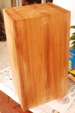
First two pics are of my new stand (with two of the three sections, If I was outside I could make it almost 2M tall!), and then one of the veneered box. I rubbed it down with a cloth damped with 90% water and 10% glycerine before taking the shot (already drying in places) to make the grain show a little better. I think I did an ok job of matching the grain from the side and top pieces.
Tony.
Also learned that I should start in the middle and work out to the end when going with the grain (still making sure to go in the opposite direction to the bit's rotation). luckily that split off was at the front which is going to be chamfered.... It does make me wonder whether I have glued properly or not. Certainly no problems with bubbles or unevenness though.
I also had a flash of inspiration yesterday. We had a floor lamp which was starting to show signs of becoming dangerous.. strange popping noises (and intermittently working... It was sitting out on the balcony waiting for a chance to dismantle to a size that could be disposed of. Then I noticed that it unscrewed, and that the actual shaft was pretty strong stainless steel. It had a big bolt on the bottom and a bracket on the top. I've been thinking I have to make a speaker testing stand for some time, and I Had been thinking that the balcony was the place to do it, but I hadn't worked out how I would make something sturdy enough to hold the speaker at a reasonable height... Then I decided to see whether I could attach the bolt to the drain grill on the balcony floor.. voila!!!! All I need to do is screw my veneer caul (for the tops of the boxes) to the bracket and I have my stand
I wouldn't be game to use it on a windy day (not that I could take measurements in the wind anyway). And it might be a challenge to find a still time when there is no other road noise etc, but I think I will now be able to take some measurements that may have a fighting chance of being at least half way decent... if I place the stand carefully (I can basically lift any tile on the bacony and put my stand there) I should be able to position so that I have oblique reflecting surfaces behind the speaker and NO reflecting surfaces behind (or above) the mike... First two pics are of my new stand (with two of the three sections, If I was outside I could make it almost 2M tall!), and then one of the veneered box. I rubbed it down with a cloth damped with 90% water and 10% glycerine before taking the shot (already drying in places) to make the grain show a little better. I think I did an ok job of matching the grain from the side and top pieces.
Tony.
Attachments
Last edited:
OK well I trimmed the veneer on the second box, all was not well after I foolishly glued on one of the pannels last weekend in 30+ degree heat. The iron fixed most of it, and what it didn't some selleys shockproof superb glue did (great stuff that). I also patched up a couple of chunks that had come out of the top pannel when trimming before, not perfect but a lot better than it was (the superglue came to the rescue there too.)
So after trimming I decided it was time to get serious (well somewhat) about sanding. I went over the whole box with some 240 grit on the random orbit, then with some 400 on the random orbit, and finally with some 1200 and a sanding block... I think possibly I should have spent longer with the 240 and 400, or maybe used 600 before the 1200, but still the results are encouraging. I was really surprised at how much the colour came up after I hit it with the 1200! prior to that the colour was lighter and the grain not very obvious. The 1200 is definitely a must
I bought myself a 500 mL tin of organoil Hard Burnishing Oil on Sat but it might be a few weeks before I get the chance to apply it, but considering how good it is looking without anything other than sanding, I think it is going to come up nicely. The main problem with the oil is I need to know I will have the time to finish it once I start it, and next weekend this is unlikely, It may even be not till after Christmas, but I'll see how I go.
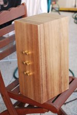
anyway obligatory picture attached I decided to put the terminals on just for show The colour might not be 100% as the white-balance was set on flash, just realised, but to my colour blind eyes it looks ok...
Tony.
So after trimming I decided it was time to get serious (well somewhat) about sanding. I went over the whole box with some 240 grit on the random orbit, then with some 400 on the random orbit, and finally with some 1200 and a sanding block... I think possibly I should have spent longer with the 240 and 400, or maybe used 600 before the 1200, but still the results are encouraging. I was really surprised at how much the colour came up after I hit it with the 1200! prior to that the colour was lighter and the grain not very obvious. The 1200 is definitely a must
I bought myself a 500 mL tin of organoil Hard Burnishing Oil on Sat but it might be a few weeks before I get the chance to apply it, but considering how good it is looking without anything other than sanding, I think it is going to come up nicely. The main problem with the oil is I need to know I will have the time to finish it once I start it, and next weekend this is unlikely, It may even be not till after Christmas, but I'll see how I go.
anyway obligatory picture attached
I decided to put the terminals on just for show The colour might not be 100% as the white-balance was set on flash, just realised, but to my colour blind eyes it looks ok...Tony.
Attachments
They are coming along nicely Tony. Nice matching of the grain!
B4 you start buying x-over parts lets have a discussion about what your goals are and what you can try. I now use the MW144 as the only midwoofer I use, that, after years of testing hundreds of drivers from mostly Europe. In the meantime get two 3.3uF caps please, reasonable quality.
Terry
B4 you start buying x-over parts lets have a discussion about what your goals are and what you can try. I now use the MW144 as the only midwoofer I use, that, after years of testing hundreds of drivers from mostly Europe. In the meantime get two 3.3uF caps please, reasonable quality.
Terry
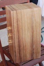
Hi Terry Thanks, I was pretty pleased with the job I did of matching up the grain I basically used one continuous piece up one side, across the top and down the other side. Back doesn't match, but I wasn't too fussed about that so didn't try. It's not perfect because I used about 5mm over (for trimming) on each side but still works quite well.
I probably have a couple of 3.3uf Polypropylenes I purchased from Wagner about 4 years back. I actually purchased a bunch of caps, I think polyprops up to about 6.8uf and then even more bi-polar electros (just for testing purposes) along with a quite a few different values of 10W non-inductive resistors, ranging from about 0.1 ohms up to a few ohms.. they are stashed away somewhere.
I think I might have mentioned before that when I did the prototype I ran it with just a cap (I think it was a 6.8uF, but my measurements just say with cap, not what value cap doh)... and the woofers running full range and that was very natural sounding. I tried putting a coil on the woofer but it resulted in wierd distortion on certain tracks (it was just a cheapy off the shelf from jaycar one)... Also played with impeadance comp on the woofer but didn't like the results, but that could have been because I didn't optomise it properly.
The plan is to cross actively to my 10" vifa woofers at around 200Hz, I'm hoping to do that with a B1 as per jaques thread.
For the MTM's I like the idea of first order if I can get away with it, but if not then nothing higher than a second order (electric) probably, as I'd like to keep it simple.
The original plan was to try crossing at around 3K, but I've also toyed with the idea of an asymetric crossover point, as I seem to have a big dip around 2K, but that may change after I do some new measurements. I don't know if you remember, but I sent you a photo (about four years ago) of my measurement setup, it was truely awful but was the best I could do at the time, you rightfully pointed out that it was less than adequate ... I'll hopefully do some new measurements before too long I suspect that my dip is baffle geometry related.
Tony.
I basically used one continuous piece up one side, across the top and down the other side. Back doesn't match, but I wasn't too fussed about that so didn't try. It's not perfect because I used about 5mm over (for trimming) on each side but still works quite well. I probably have a couple of 3.3uf Polypropylenes I purchased from Wagner about 4 years back. I actually purchased a bunch of caps, I think polyprops up to about 6.8uf and then even more bi-polar electros (just for testing purposes) along with a quite a few different values of 10W non-inductive resistors, ranging from about 0.1 ohms up to a few ohms.. they are stashed away somewhere.
I think I might have mentioned before that when I did the prototype I ran it with just a cap (I think it was a 6.8uF, but my measurements just say with cap, not what value cap doh)... and the woofers running full range and that was very natural sounding. I tried putting a coil on the woofer but it resulted in wierd distortion on certain tracks (it was just a cheapy off the shelf from jaycar one)... Also played with impeadance comp on the woofer but didn't like the results, but that could have been because I didn't optomise it properly.
The plan is to cross actively to my 10" vifa woofers at around 200Hz, I'm hoping to do that with a B1 as per jaques thread.
For the MTM's I like the idea of first order if I can get away with it, but if not then nothing higher than a second order (electric) probably, as I'd like to keep it simple.
The original plan was to try crossing at around 3K, but I've also toyed with the idea of an asymetric crossover point, as I seem to have a big dip around 2K, but that may change after I do some new measurements. I don't know if you remember, but I sent you a photo (about four years ago) of my measurement setup, it was truely awful but was the best I could do at the time, you rightfully pointed out that it was less than adequate
... I'll hopefully do some new measurements before too long I suspect that my dip is baffle geometry related. Tony.
When you get to mounting drivers and listening, I would like you to // the woofers and then feed the tweeter via a single 3.3 uf cap. This is possible only with this combination of drivers. I have never found any other drivers that this is possible for.
MW168 comes close but requires a small inductor. If you want to try an inductor and there is no reason not to try, add 0.1 mH.
This series from Morel don't need and don't respond well to impedance compensation nor do they work well with second order or greater.
Just as an example, Vifa and scanspeak don't do well with first order at all.
The marriage of the DMS37 and MW144 is made in heaven, as they should be, the DMS37 was designed just for this purpose.
Terry
- Status
- This old topic is closed. If you want to reopen this topic, contact a moderator using the "Report Post" button.
- Home
- Loudspeakers
- Multi-Way
- My Morel MTM Project