I liked the blog, Tony. I have seen builders adding bucketloads of passive components into an xover just to save a wide 1dB lift. I like my xovers simple if it can be done. When you have finished yours, compare them with the simple 5.6 or 6.8uF and see what they sound like. Just for fun! ")
Terry
Terry
Tony, just a suggestion, when you cross to your tens, do it at 300Hz but no higher. That leaves the mid woofer to handle all the human voice and at the same time minimises cone excursion. As far as the tens are concerned you will come very close to providing baffle step compensation (If you think it is important) by simply turning up the bass amp.
Terry
Terry
Thanks Terry, I've at various times thought about crossing at 300Hz but when I looked at my original design calcs I had done it was actually planned for 200Hz. The BSC I was contemplating putting into the active crossover has a pot meaning it can be adjusted from 0db right through 6db, excellent for experimenting. I did originally intend to not do any BSC on the MTM's but after seeing the measurements thought maybe a little might be in order.
I will have to try the suggestion of reducing the parts count. Certainly I've done that already (removing the 1k notch, which took out three parts) The resulting graph doesn't look as smooth, but they sound better
I actually decided to start a blank speaker workshop project and re-imported my measurements (individual drivers and the combined response with the current crossover) at least for this crossover the simulation is VERY good. I'll have to try again with the higher order and see if the funnyness persists (but now it is time for bed).
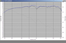
Hows this for a correlation between sim and actual measured response? Black is the sim, and Blue is the actual measured response. all measurements were done with the mic and speaker in the exact same position, crossover was already made, just swapped the wires for the three measurements, and then simmed the actual built crossover with the individual tweeter and woofer responses to get a comparison. Pretty damn close!! If I can get that good a correlation for the 4th order network I'll be very happy
Tony.
I will have to try the suggestion of reducing the parts count. Certainly I've done that already (removing the 1k notch, which took out three parts) The resulting graph doesn't look as smooth, but they sound better
I actually decided to start a blank speaker workshop project and re-imported my measurements (individual drivers and the combined response with the current crossover) at least for this crossover the simulation is VERY good. I'll have to try again with the higher order and see if the funnyness persists (but now it is time for bed).
Hows this for a correlation between sim and actual measured response? Black is the sim, and Blue is the actual measured response. all measurements were done with the mic and speaker in the exact same position, crossover was already made, just swapped the wires for the three measurements, and then simmed the actual built crossover with the individual tweeter and woofer responses to get a comparison. Pretty damn close!! If I can get that good a correlation for the 4th order network I'll be very happy
Tony.
Attachments
Thanks Dan,
I have to make a correction to the above post though. This bit When I took 1M and 1.5M measurements on anly particular day there were only very minor differences.
I ended up using the 1.5M measurements because they were the ones I did with time zero locked in holm impulse (and I didn't go back and do 1M ones). This made a big difference for getting accurate sim results, as before I did this, there was only a minor correlation between the sim and the actual results.
Tony.
I have to make a correction to the above post though. This bit
Is not correct. It is what I did initially, but I changed the crossover since, and the above is with the latest version of the crossover. I was tired last night. The actual measured response was in fact done a few months after the initial driver responses, and was an on axis one meter measurement, whereas the measurements of the drivers individually were taken at 1.5M. Also for clarification when I say individual drivers, the MW144's were running together and the measurement was taken on axis with the tweeter (ie in the centre of the two drivers). so by individual I mean separate measurements of the tweeter and the MW144 pairall measurements were done with the mic and speaker in the exact same position, crossover was already made, just swapped the wires for the three measurements, and then simmed the actual built crossover with the individual tweeter and woofer responses to get a comparison.
When I took 1M and 1.5M measurements on anly particular day there were only very minor differences. I ended up using the 1.5M measurements because they were the ones I did with time zero locked in holm impulse (and I didn't go back and do 1M ones). This made a big difference for getting accurate sim results, as before I did this, there was only a minor correlation between the sim and the actual results.
Tony.
Last edited:
woops!
I've spent an awful lot of time simulating a new crossover, but I hadn't ticked the box to simulate the impedance... what a mistake!! luckily I've been procrastinating and hadn't bought the components for the 4th order network.
The impedance curve of what I'd pretty much settled on is terrible. around 1.3 ohms at 800Hz.... Back to the drawing board!!
Tony.
Attachments
My goodness it's been nearly a year since I posted here!! scarily I haven't done anything much at all. The speakers are fine (more than fine) for TV and watching movies which is their main duty, however I've not been satisfied with them for certain music. Ironically I think one of the earlier incarnations of the crossover was better.
My interest has been re-kindled by the can you have sparkling treble but without silibance thread and more specifically by a post that Lynn Olsen made #17
I think that my crossover point is too low, and I'm getting modulation of the higher frequencies from the lower frequencies that the tweeter is trying to produce.
I did some measurements on the weekend and have attached some below.
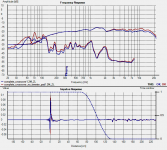
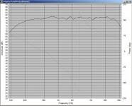
The first pic shows the measurements of the MW144's and the DMS37. I used swept sine at 1.2M distance, and starting frequency of 100Hz.
The second pic shows measurements with (blue) and without (red) the padding on the tweeter.These are actual measurements of the speaker with the current crossover.
The orange trace is the result of measuring each of the tweeter and mids with their respective crossover components individually and then summing the response (with tweeter inverted) in holmimpulse. I didn't think to do ta crossover measurement with tweeter inverted on the day.
What this tells me is that the crossover frequency is actually lower than I thought, (it was supposed to be 3Khz originally) at around 2.2Khz, it also indicates that the tweeter is contributing to the overall sonics down to a shockingly low 600Hz
The speakers sound great on some music, but terrible on others, it was Lynns comment on dense material that made the penny drop.
Picture three shows the THD plots for the current implementation...
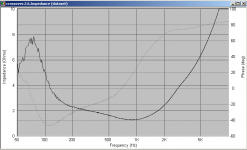
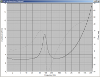
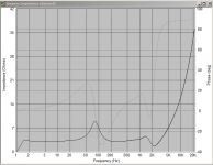
The fourth picture is the impedance plot of the MW144's measured in the exact same position that the acoustic measurements were taken. The thing I find most strange about this is that it shows no signs of anomalies in the 1-4khz region.
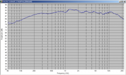
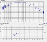
The 5th picture is a nearfiled measurement of one of the two MW144's taken a while ago, and yes that is the raw response, no gating no smoothing.
Anyway I have some more work to do and now at least I have an idea what to focus on, for the particular problem my ears were telling me I had
Tony.
My interest has been re-kindled by the can you have sparkling treble but without silibance thread and more specifically by a post that Lynn Olsen made #17
I think that my crossover point is too low, and I'm getting modulation of the higher frequencies from the lower frequencies that the tweeter is trying to produce.
I did some measurements on the weekend and have attached some below.
The first pic shows the measurements of the MW144's and the DMS37. I used swept sine at 1.2M distance, and starting frequency of 100Hz.
The second pic shows measurements with (blue) and without (red) the padding on the tweeter.These are actual measurements of the speaker with the current crossover.
The orange trace is the result of measuring each of the tweeter and mids with their respective crossover components individually and then summing the response (with tweeter inverted) in holmimpulse. I didn't think to do ta crossover measurement with tweeter inverted on the day.
What this tells me is that the crossover frequency is actually lower than I thought, (it was supposed to be 3Khz originally) at around 2.2Khz, it also indicates that the tweeter is contributing to the overall sonics down to a shockingly low 600Hz
The speakers sound great on some music, but terrible on others, it was Lynns comment on dense material that made the penny drop.
Picture three shows the THD plots for the current implementation...
The fourth picture is the impedance plot of the MW144's measured in the exact same position that the acoustic measurements were taken. The thing I find most strange about this is that it shows no signs of anomalies in the 1-4khz region.
The 5th picture is a nearfiled measurement of one of the two MW144's taken a while ago, and yes that is the raw response, no gating no smoothing.
Anyway I have some more work to do and now at least I have an idea what to focus on, for the particular problem my ears were telling me I had
Tony.
Attachments
Thanks DrDyna yes it has been over about 5 years (8 years if you count the three years thinking about it before buying the drivers ) though there was a big gap there where I did nothing at all...
Some of my cd's sound very good on them, but some are pretty much unlistenable I reaaly find myself wanting to turn it down or completely off after only a few seconds. This is what I want to fix
and you are right (as is Terry) I do tend to over engineer... always striving for perfection I was focusing on getting a flat frequency response before, which is I now suspect and as Terry already pointed out, not an area I need to worry about
Tony.
yes it has been over about 5 years (8 years if you count the three years thinking about it before buying the drivers ) though there was a big gap there where I did nothing at all... Some of my cd's sound very good on them, but some are pretty much unlistenable I reaaly find myself wanting to turn it down or completely off after only a few seconds. This is what I want to fix
and you are right (as is Terry) I do tend to over engineer... always striving for perfection
I was focusing on getting a flat frequency response before, which is I now suspect and as Terry already pointed out, not an area I need to worry about Tony.
Hi Terry I know it shouldn't be there, but it is try as I may to change my measurement setup it always remains, sometimes it changes a little but it doesn't change much.
When I was looking for other measurements I thought that I found one of my vifa 10" that was showing similar tendencies but I checked the original measurements and not so.
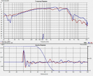
Below graph shows Vifa 10" red vs the MW144's blue, levels adjusted to get the curves close to each other. As you can see the vifa is showing no signs of a problem in the 2Khz region. These were both measured in the same spot (well as close as possible considering the considerable difference in size of the enclosures) on my balcony about 6 months ago. O think this shows that it isn't the mic or the measuring setup that is causing the dip on the MTM's it is something with the actual speaker, but try as I have I have not been able to work out what...
I think it improved a bit when I took more material out around the back of the cutout, perhaps I still need to do more. However even a measurement done boxless shows some of the same tendencies, however that was a nearfield measurement, I should have done a 1M one (or perhaps 50cm).
The datasheet for the MW144 on morel Israel's site actually shows a 5db suck out at 1Khz somewhat like what I'm seeing at 2Khz, I know the older datasheets showed a much smoother response though.
My too low crossover point has resulted from tweaking the crossover to get the smoothest response I can with this dip there. That's why I guess I have a much bigger cap than you thought I should need. 4.6uF vs 3.3uF...
Perhaps I should try ignoring the dip and shift my crossover point up. the measurements might look ugly but the sound may improve, only one way to find out
edit: reason for the high gating was that the vifa was too big to put on my stand, so was closer to the ground than ideal, only about 0.8M off the ground instead of the usual 1.4M that I do the MTM's at.
Tony.
try as I may to change my measurement setup it always remains, sometimes it changes a little but it doesn't change much. When I was looking for other measurements I thought that I found one of my vifa 10" that was showing similar tendencies but I checked the original measurements and not so.
Below graph shows Vifa 10" red vs the MW144's blue, levels adjusted to get the curves close to each other. As you can see the vifa is showing no signs of a problem in the 2Khz region. These were both measured in the same spot (well as close as possible considering the considerable difference in size of the enclosures) on my balcony about 6 months ago. O think this shows that it isn't the mic or the measuring setup that is causing the dip on the MTM's it is something with the actual speaker, but try as I have I have not been able to work out what...
I think it improved a bit when I took more material out around the back of the cutout, perhaps I still need to do more. However even a measurement done boxless shows some of the same tendencies, however that was a nearfield measurement, I should have done a 1M one (or perhaps 50cm).
The datasheet for the MW144 on morel Israel's site actually shows a 5db suck out at 1Khz somewhat like what I'm seeing at 2Khz, I know the older datasheets showed a much smoother response though.
My too low crossover point has resulted from tweaking the crossover to get the smoothest response I can with this dip there. That's why I guess I have a much bigger cap than you thought I should need. 4.6uF vs 3.3uF...
Perhaps I should try ignoring the dip and shift my crossover point up. the measurements might look ugly but the sound may improve, only one way to find out
edit: reason for the high gating was that the vifa was too big to put on my stand, so was closer to the ground than ideal, only about 0.8M off the ground instead of the usual 1.4M that I do the MTM's at.
Tony.
Attachments
Last edited:
Is that response with or without x-over components. I have measured many MW144s and never had a dip of this sort of magnitude. That is 10dB! It's like a deep ocean trench. Look at box dimensions and driver to edge dimensions. If it was purely driver related I would expect to see a glitch in the Z graph.
Terry
Terry
Hi Terry, without crossover, and yes that's exactly what I thought, why no impedance glitch. The simulation for baffle step shows a dip at 2Khz and the rise from 1Khz but no where near what is present.
I just checked and the centre of the dip is around 2175 Hz. that is 157mm which is pretty much exactly the width of the baffle (to where the chamfer starts) the total box width is 200mm. It is also (in an unfortunate twist) almost exactly the distance from the bottom or top edge of the surround of the MW144's to the top or bottom chamfer of the box... Not something I considered when doing the design, I might have to get my original prototype box and doing some measurements with it, as it was taller and narrower than the current boxes. I really really don't want to redo these boxes though
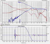
I had a go at another simulation of a 4th order (acoustic) L/R crossover. looked good till I checked the impedance curve...
1st pic is the combined simulated response second pic is the simulated impedance for the low pass
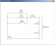
3rd pic is my attempt at the lowpass filter, basically a low Q notch at 1.45Khz and then something resembling a 2nd order filter after that... perhaps some playing with inductor and capacitor values can get rid of the impedance dip at 2Khz... damn that 2Khz!! The 99 milliohms in series with the cap is to stop speakerworshop from creating a resonance between the cap and the coil.
Tony.
I just checked and the centre of the dip is around 2175 Hz. that is 157mm which is pretty much exactly the width of the baffle (to where the chamfer starts) the total box width is 200mm. It is also (in an unfortunate twist) almost exactly the distance from the bottom or top edge of the surround of the MW144's to the top or bottom chamfer of the box... Not something I considered when doing the design, I might have to get my original prototype box and doing some measurements with it, as it was taller and narrower than the current boxes. I really really don't want to redo these boxes though
I had a go at another simulation of a 4th order (acoustic) L/R crossover. looked good till I checked the impedance curve...
1st pic is the combined simulated response second pic is the simulated impedance for the low pass
3rd pic is my attempt at the lowpass filter, basically a low Q notch at 1.45Khz and then something resembling a 2nd order filter after that... perhaps some playing with inductor and capacitor values can get rid of the impedance dip at 2Khz... damn that 2Khz!!
The 99 milliohms in series with the cap is to stop speakerworshop from creating a resonance between the cap and the coil. Tony.
Attachments
Hi Terry, I've actually been considering going back to that implementation in post 73/4 I got rid of the approximately 1K notch filter because it seemed to be introducing distortion, it could have been the cheap 100uf electrolytic I was using!
I'm generally happy with the sound, but some of my favourite albums sound really quite bad, Lynn Olsons comment about dense material causing tweeter distortion made me rethink a bit, which is what prompted me to start searching for a solution again. There is something not right because even at moderate volume (certainly not loud) my ears start to hurt with some cd's, I'm pretty sure that never happened with my old three ways which were far from optimal
After doing some more simulation I found though that the crossover point should be 3Khz, it is just that the dip at 2.2Khz make it look like that's the null point when the tweeter is reversed.
Have you ever put a resonant peak filter on the morel tweeters? It's something I'm considering trying.
Currently I'm listening with the tweeter pad removed, and whilst I can hear a little silibance it isn't bad, and I think the voices (It's playing TV at the moment) sound more natural.
I hear you!! I've stopped obsessing about flat frequency response (though that 1-2K bump does still bug me a bit) Just want to find what the source of that something that doesn't quite sound right is. If you weren't in Adelaide, I'd be asking you to come over and take a listen, then you would be able to tell me if I'm tilting at windmills or not Of course there is also the possibility it is my room to a degree as well. It certainly isn't as good as the one I used to have before I finished these speakers
Tony.
I'm generally happy with the sound, but some of my favourite albums sound really quite bad, Lynn Olsons comment about dense material causing tweeter distortion made me rethink a bit, which is what prompted me to start searching for a solution again. There is something not right because even at moderate volume (certainly not loud) my ears start to hurt with some cd's, I'm pretty sure that never happened with my old three ways which were far from optimal
After doing some more simulation I found though that the crossover point should be 3Khz, it is just that the dip at 2.2Khz make it look like that's the null point when the tweeter is reversed.
Have you ever put a resonant peak filter on the morel tweeters? It's something I'm considering trying.
Currently I'm listening with the tweeter pad removed, and whilst I can hear a little silibance it isn't bad, and I think the voices (It's playing TV at the moment) sound more natural.
I hear you!! I've stopped obsessing about flat frequency response (though that 1-2K bump does still bug me a bit) Just want to find what the source of that something that doesn't quite sound right is. If you weren't in Adelaide, I'd be asking you to come over and take a listen, then you would be able to tell me if I'm tilting at windmills or not
Of course there is also the possibility it is my room to a degree as well. It certainly isn't as good as the one I used to have before I finished these speakers Tony.
Attachments
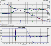
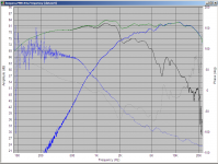
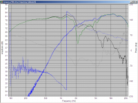
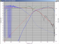
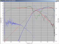
Thanks Terry. I did some more sims last night which I think are helping to narrow down the problem. I think the issue is with the phase in the crossover region. with the current implementation (and I'd swear last night the sim showed an exact phase match at 2Khz but it doesn't now) the phase tracking is a bit off. I made some changes to the high pass network and got a better phase tracking through the crossover region, but with the result that the big hole at 2Khz is now very obvious. I suspect however overall it should be better.
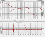
Note that all below are 2nd order bessel at 3Khz green is the summed response.
1st pic current crossover showing filtered low and high responses with phase, and green the summed response.
2nd pic as above with the tweeter reversed.
3rd pic high pass network modified to vary the phase still 3Khz end order bessel acoustic.
4th pic as above but tweeter reversed.
5th pic is the original vs new sim response.
I'll continue to play with trying to get the phase match better, I suspect this is where my problems are coming from, not from too low a crossover frequency as I thought it might be.
Tony.
Attachments
Last edited:
- Status
- This old topic is closed. If you want to reopen this topic, contact a moderator using the "Report Post" button.
- Home
- Loudspeakers
- Multi-Way
- My Morel MTM Project