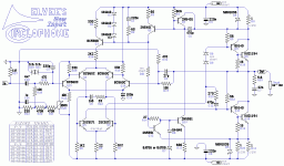
The new input from Keantoken worked just like. . .

. . . it worked just like he said it would. It grafts onto Standard Circlophone (post 1 on this thread) seamlessly. The main benefit is compatibility with lossy sources and volume knobs, without having to build a preamp or buffer. The side benefit is unlocked future development due to generally improved tolerances. And, board layout with this input can be easily jumpered back to Standard Circlophone if desired, just by reconnecting IN+ and IN- per the standard schematic. Just one board can do both options. Terranigma, its your turn.That said, a darlington input like this one will raise the input impedance and eliminate the bias current modulation effects, practically without drawback.
. . . it worked just like he said it would. It grafts onto Standard Circlophone (post 1 on this thread) seamlessly. The main benefit is compatibility with lossy sources and volume knobs, without having to build a preamp or buffer. The side benefit is unlocked future development due to generally improved tolerances. And, board layout with this input can be easily jumpered back to Standard Circlophone if desired, just by reconnecting IN+ and IN- per the standard schematic. Just one board can do both options. Terranigma, its your turn.
Good news as usual.. Since that I'm making changes on layout manually, I need some time for prepare something usable.
Last edited:
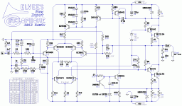
Well, I just got an epic workout and sore fingers from making a new schematic.Good news as usual.. Since that I'm making changes on layout manually, I need some time for prepare something usable.
Could you check it out and see if I've implemented the new input system right?
Attachments
DC feedback. Interesting. I predict you ill have a falling output voltage ith temperature, since the LTP base impedances are't matched. It ill probably be small because R20 is small but it ill be there. Offset ill also change ith rail voltage, but I think this ill also be small. I see the compensation scheme has not changed.
keantoken said:DC feedback. Interesting. I predict you will have a falling output voltage with temperature, since the LTP base impedances are't matched. It will probably be small because R20 is small but it will be there. Offset will also change with rail voltage, but I think this will also be small. I see the compensation scheme has not changed.
One possible option for the similar gain setting AND similar base impedances is:
R20, 12K
R19, 330R
R17, 12K
R16, 330R
Any problems with doing this?
Last edited:
Q15's base sees 12k to ground. Q14's base sees 390R to ground. Traditionally this is solved by putting a cap in series ith R16. Furthermore, I've realized the offset may be much orse. 1mV offset ill be amplified by your gain, to be 40mV or something. ithout base impedance matching or some sort of compensation your offset may ander all over. Multiplying R28/R29 by 4 might not even help, unless the input stage is matched.
PS: Miller action blos up C4 to 830pF. So 820pF for C5 may be orth experimenting ith to see if the balance brings ne sonic qualities.
I don't kno the capacitance of zeners offhand, but the input zeners may be a significant source of nonlinear capacitance. Putting them in parallel ith 1N4148 or BAT54 in series ith them individually ill reduce the amount of nonlinear capacitance seen at the input. Furthermore, R34 presents the opportunity for a 2nd-order input LP, far more effective than first order, at RF filtering. This means an additional cap across the zeners.
But ait there's more! If you make R34 82R and put a 220p capacitor across the zeners, you ill be giving your input cables a termination netork hich prevents them from resonating and causing RF ingress or oscillation.
Just so you are aare of the possibilities.
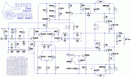
Okay, howabout this?
One possibility to equalize the offset voltage is to insert a 12k paralleled with 4µ7 in Q14's base.
Okay, howabout this?
Adding a parallel C-R circuit at NFB for avoiding cap at negative input doesn't seem to me a relevant way for abide purpose. I may be wrong but I actually prefer keep simple as much as possible NFB.
Adding a parallel C-R circuit at NFB for avoiding cap at negative input doesn't seem to me a relevant way for abide purpose. I may be wrong but I actually prefer keep simple as much as possible NFB.
If I put 10k parallel to the NFB cap it wouldn't have equalized the load on both transistor bases, right?I as sorta thinking the same thing. You trade an electrolytic for a film. It may be ugly, but maybe it's orth it?
If we're stuck with the input circuit, I can simply return the NFB cap and leave the trimmer on the schematic; however, there's a lot that doesn't do.
Well, yes. That's the step out after this one. I'd like to do that without adding a lot more transistors.I also wonder why we shouldn't re-adjust compensation values of original Circlophone respecting new buffer/input implementation. Is it possible to adjust compensations for getting any advantage in terms of output device variety, flexibility, etc?
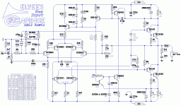
New input now simplified. Needs checked.
Okay, NFB cap has returned and the protection diodes have increased to 1v, which may or may not give enough tolerance to avoid offset bounce. The static protected BAT86 are unlikely to misfire, but I have a question: Are the BAT86 durable enough for this or do I need a pair of FR/BY or similar fast silicon to get the 1v figure?
The resulting schematic is much simplified. If the input circuit passes your inspection, then I can begin work on minor compensation adjustments for phase linear up to 1.5mhz, without further increasing the transistor count. To make this sync up, I'll have to put MJ15003G or similar speed output, devices in the simulator, and then compensation adjustments, can then be quite mild, without the complexity we saw earlier. I'm trying for minimal modifications this time. But, first, an input. . . (see attachment). Is this okay?
Attachments
Last edited:
- Home
- Amplifiers
- Solid State
- ♫♪ My little cheap Circlophone© ♫♪


